Isuzu KB P190. Manual — part 1000
7A2-34 TRANSMISSION CONTROL SYSTEM (AW30–40LE)
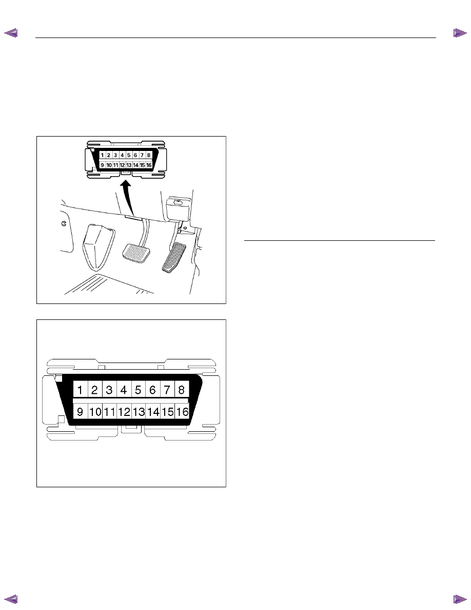
16 – Terminal Data Link Connector (DLC)
OBD standardizes Data Link Connector (DLC)
configurations. The DLC, formerly referred to as the
ALDL, will be a 16–terminal connector found on the
lower right side of the driver's side instrument panel. All
manufacturers must conform to this 16–terminal
standard.
060R300015
810RT022
PIN 1 – Diagnostic request switch
PIN 2 – J1850 Class 2
PIN 3 – (Not used)
PIN 4 – Ground
PIN 5 – Ground
PIN 6 – CAN High
PIN 7 – Keyword 2000
PIN 8 – (Not used)
PIN 9 – (Not used)
PIN 10 – (Not used)
PIN 11 – TCM diagnostic
PIN 12 – ABS diagnostic request switch
PIN 13 – SIR diagnostic request switch
PIN 14 – CAN Low
PIN 15 – (Not used)
PIN 16 – Battery voltage
TRANSMISSION CONTROL SYSTEM (AW30–40LE) 7A2-35
Clear DTC
NOTE:
If you clear the DTC (Diagnostic Trouble
Codes) you will not be able to read any codes recorded
during the last occurrence.
NOTE: To use the DTC again to identify a problem, you
will need to reproduce the fault or the problem. This
may require a new test drive or just turning the ignition
on (this depends on the nature of the fault).
1. IF you have a Tech 2:
1. Connect the Tech 2 and perform the Tech 2
Operating.
2.
Push “F1: Clear DTC Information” in the
Application Menu and answer “Yes” to the
question “Do you want to clear DTC's?”
a. When a malfunction still exists and the Tech
2 displays “AW30-40 CODES NOT
CLEARED”. This means that the problem is
still there or that the recovery was not done.
Please go to DTC Check.
b. When a malfunction has been repaired and
the recovery is done the Tech 2 displays
“AW30-40LE CODES CLEARED”.
2. When you have no Tech 2, the storaged trouble
codes can be cleared by shorting the terminals
No.11 and No.4 or 5 (ground) of data link connector
with a lead wire for 1
∼
6 seconds.
DTC Check
1.
Diagnostic Trouble Codes (DTC) have been
identified by Tech 2.
2. You have written the list of the DTCs. The order of
the malfunctions has no meanings for this TCM.
Usually only one or two malfunctions should be set
for a given problem.
3. Check directly the DTCs you identified. The DTCs
are sorted by number. Refer to Diagnostic Trouble
Code (DTC) Identification in this section.
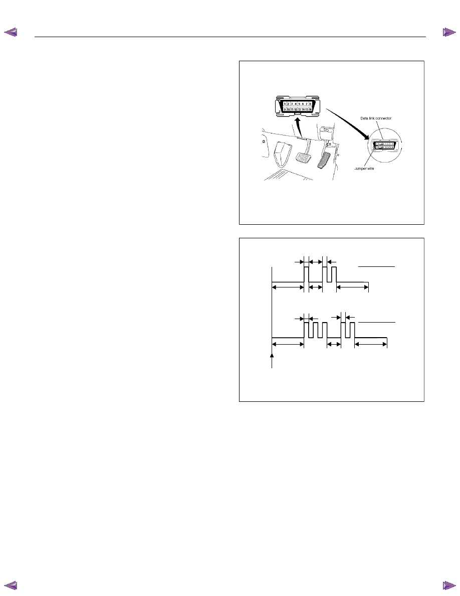
Self-diagnosis code (Flash code) display
• The stored trouble codes can be identified by
shorting the terminal No. 11 and No. 4 or No. 5
(ground) data link connector with a lead wire.
Indication Method:
1. Terminal No. 11 and No. 4 or No. 5 (ground) data
link connector are short circuited.
2. Turn the key switch to the ON position.
3. If no trouble code exists, the normal code (12) is
indicated repeatedly.
Data Link Connector Short Circuit
Flash Code Illumination Pattern
0.4 Sec 0.4 Sec
.
ON
OFF
3.2 Sec. 1.2 Sec. 3.2 Sec.
0.4 Sec 0.4 Sec
.
ON
OFF
3.2 Sec. 1.2 Sec. 3.2 Sec.
Self-diagnosis Start
Normal Code (12)
Trouble Code (32)
4. If several trouble codes have occurred at a time,
each code is indicated three times in numerical
order.

7A2-36 TRANSMISSION CONTROL SYSTEM (AW30–40LE)
Trouble Code Clear Method:
If you have Tech 2:
Follow the procedure "DIAGNOSIS WITH TECH 2" in
this manual.
If you have no Tech 2:
Remove ECM (B) fuse (10A) for at least 10 seconds
with the ignition switched off.
NOTE:
If you clear the DTC you will not be able to read any
codes recorded during the last occurrence.
To use the DTC again to identify a problem, you will
need to reproduce the fault or the problem. This may
require a new test drive or just turning the key switch on
(this depends on the nature of the fault).
12
14
14
14
32
32
32
In case DTC 14 & 32 are stored:
TCM Precaution
The TCM can be damaged by:
1. The electrostatic discharge
2. The short circuit of some terminals to voltage or to
ground.
Electrostatic Discharge Damage Description:
1. Electronic components used to control systems
are often designed to carry very low voltage, and
are very susceptible to damage caused by
electrostatic discharge. It is possible for less than
100 volts of static electricity to cause damage to
some electronic components. By comparison, it
takes as much as 4,000 volts for a person to even
feel the zap of a static discharge.
2. There are several ways for a person to become
statically charged. The most common methods of
charging are by friction and induction. An example
of charging by friction is a person sliding across a
car seat, in which a charge of as much as 25,000
volts can build up. Charging by induction occurs
when a person with well insulated shoes stands
near a highly charged object and momentarily
touches ground. Charges for the same polarity are
drained off, leaving the person highly charged with
the opposite polarity. Static charges of either type
can cause damage, therefore, it is important to use
care when handling and testing electronic
components.
NOTE: To prevent possible electrostatic discharge
damage:
1. Do not touch the TCM connector pins or soldered
components on the TCM circuit board.
2. Be sure to follow the guidelines listed below if
servicing any of these electronic components:
3. Do not open the replacement part package until it is
time to install the part.
4. Avoid touching electrical terminals of the part.
5. Before removing the part from its package, ground
the package to a known good ground on the
vehicle.
6. Always touch a known good ground before handling
the part. This step should be repeated before
installing the part if the part has been handled while
sliding across the seat, while sitting down from a
standing position or while walking some distance.
Information On TCM
1. The Transmission Control Module (TCM) is located
in the place of a clutch pedal and is the control
center of the electronic transmission control system.
TRANSMISSION CONTROL SYSTEM (AW30–40LE) 7A2-37
2. The TCM must be maintained at a temperature
below 85
°C (185°F) at all times. This is most
essential if the vehicle is put through a paint baking
process. The TCM will become inoperative if its
temperature exceeds 85
°C (185°F). Therefore, it is
recommended that the TCM be removed or that
temporary insulation be placed around the TCM
during the time the vehicle is in a paint oven or other
high temperature process.
3. The TCM is designed to process the various inputs
and then respond by sending the appropriate
electrical signals to control transmission upshift,
downshift, shift feel and torque converter clutch
engagement.
4. The TCM constantly interprets information from the
various sensors, and controls the systems that
affect transmission and vehicle performance. By
analyzing operational problems, the TCM is able to
perform a diagnostic function by displaying DTC(s)
and aid the technician in making repairs.
Нет комментариевНе стесняйтесь поделиться с нами вашим ценным мнением.
Текст