Isuzu KB P190. Manual — part 362
6A-88 ENGINE MECHANICAL (4JK1/4JJ1)
RTW56ASH009101
Legend
1. Cylinder
Head
2. Oil Seal Installer
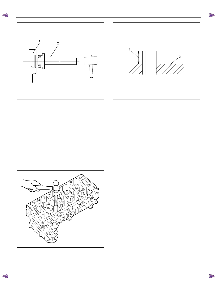
2. Install the valve guide.
• Hammer in the valve guide from the upper
surface of the cylinder head, using the valve
guide installer.
Special
tool
Valve guide remover and installer:
5-8840-2816-0
Note:
When replacing the valve guide, it must be replaced
together with the valve.
RTW56ASH009001
• Height from the upper surface of the cylinder
head to the edge surface of the valve guide
RTW56ASH023001
Legend
1. 12.6 ± 0.1 mm (0.50 ± 0.0039 in)
2. Cylinder Head
3. Install the valve spring lower seat.
4. Install the valve stem oil seal.
• Refer to procedure for valve stem and valve in
this manual.
5. Install the intake and exhaust valve.
• Apply engine oil on the valve stem part and
install the valve.
6. Install the valve spring, the valve spring upper seat
and the split collar.
• Refer to procedure for valve stem and valve in
this manual.
7. Install the rocker arm and shaft assembly.
• Refer to procedure for valve stem and valve in
this manual.
8. Install the exhaust manifold assembly.
• Refer to procedure for Turbocharger and
Exhaust Manifold in this manual.
9. Install the turbocharger.
• Refer to procedure for Turbocharger and
Exhaust Manifold in this manual.
10. Install the intake manifold assembly.
• Refer to procedure for Intake Manifold in this
manual.
11. Install the throttle assembly.
• Refer to procedure for Intake Manifold in this
manual.
ENGINE MECHANICAL (4JK1/4JJ1) 6A-89
Installation
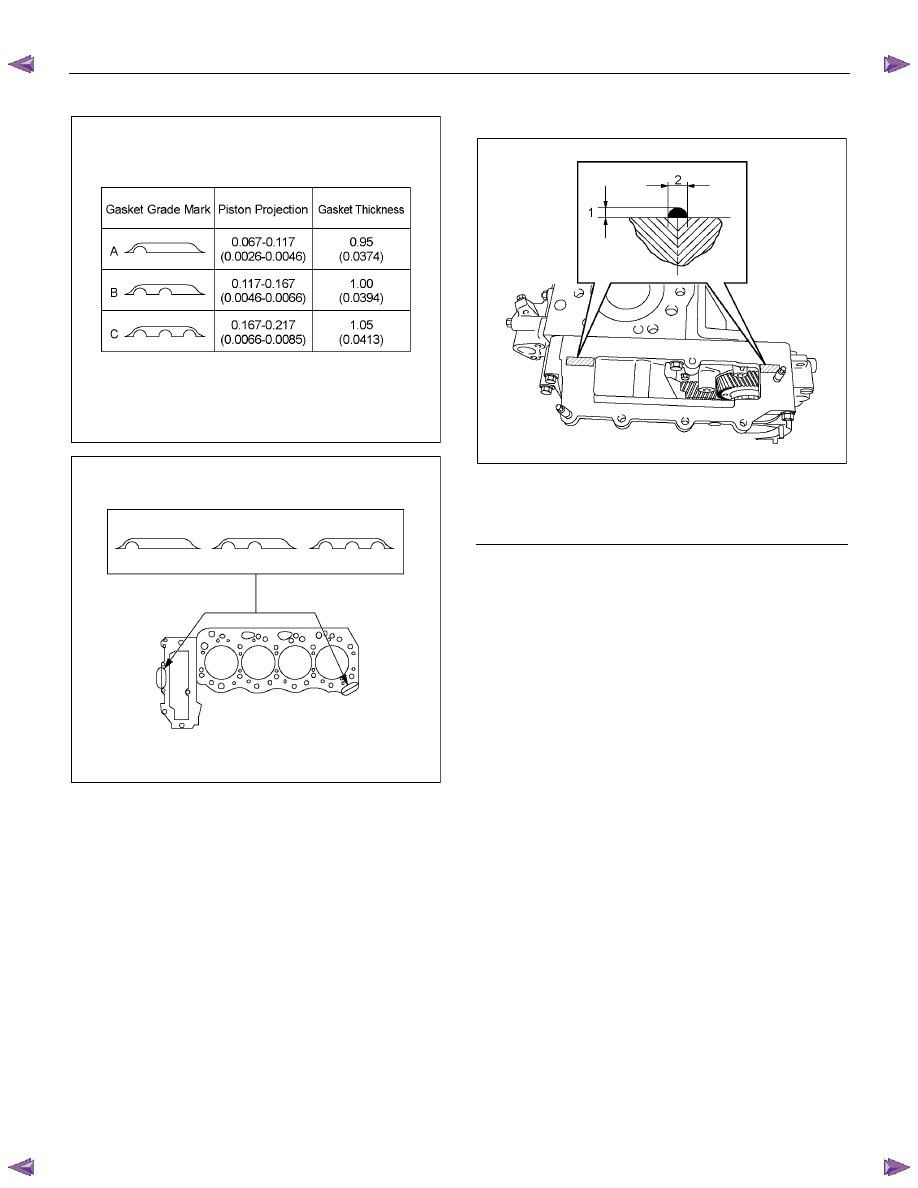
1. Select the cylinder head gasket.
Cylinder Head Gasket Selection
Cylinder head gasket is determined by the piston head
projection from the cylinder body upper surface, in order
to improve engine performance.
Three types of gasket are provided with difference of
thickness. Select the appropriate one out of three
grades of
gasket, according to the following procedure.
Before measurement, clear off carbon from the piston
head and cylinder body surface and also clean the
place where the gasket was installed.
011LX011
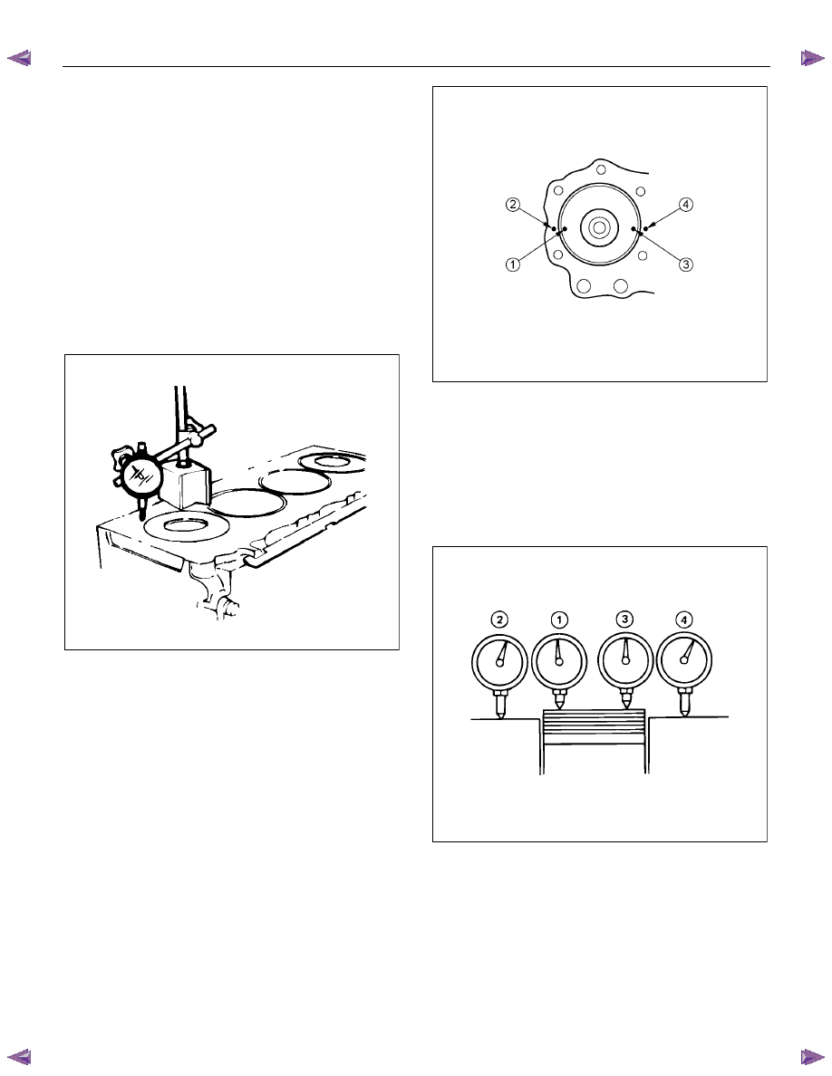
1. Use a dial indicator to measure the piston
projection amount.
2. Refer to the illustration for the piston head
projection measuring positions. All measuring
positions should be as close as possible to the
cylinder block.
RTW36ASH001701
3. Measure the points 1, 2, 3, 4 and obtain two
differences 1-2 and 3-4 on each cylinder. Calculate
the average value of the piston head projection on
each cylinder.
4. Obtain the maximum value in the four cylinders.
5. Determine the gasket grade required to the
maximum value described above in accordance
with the following table.
011RY00027
6A-90 ENGINE MECHANICAL (4JK1/4JJ1)
Cylinder Head Gasket Combination
mm (in)
RTW76ASH000301
RTW56ASH009501
Note:
Difference of each piston projection must be equal or
within 0.05 mm (0.002 in).
7. Select the gear case gasket.
• This should be of the same grade as the
cylinder gasket.
8.
Apply liquid gasket (ThreeBond 1207B
or
equivalent) at the two locations.
RTW56ASH020901
Legend
1. 2 - 3 mm (0.079 - 0.118 in)
2. 3 - 4 mm (0.118 - 0.157 in)
9.
Install the cylinder head within 5 minutes
application of the liquid gasket.
10. Install the cylinder head.
• Wipe the cylinder head lower face.
• Install the cylinder head, adjusting the dowel of
the cylinder block.
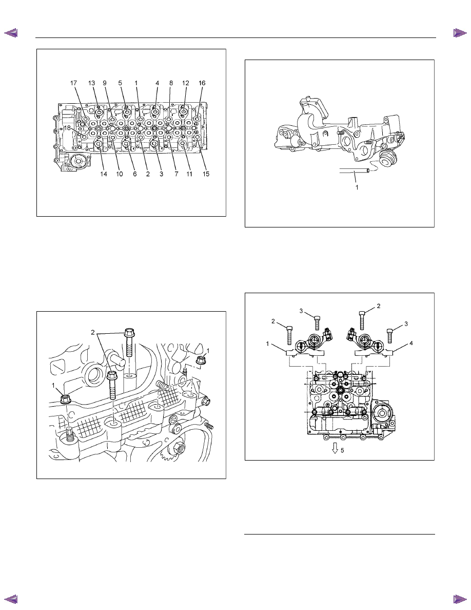
11. Install the cylinder head bolt.
• Please use new cylinder head bolt.
• Use a torque wrench and angle gauge to
tighten the head bolts in the order described in
the drawing.
Tightening torque:
1st step = 70 N
⋅⋅⋅⋅m (7.1 kg⋅⋅⋅⋅m / 51 lb ft)
2nd step = 70 N
⋅⋅⋅⋅m (7.1 kg⋅⋅⋅⋅m / 51 lb ft)
3rd step = 60° (degrees)
4th step = 60° (degrees)
ENGINE MECHANICAL (4JK1/4JJ1) 6A-91
RTW56ASH009701
Special tool
Angle gauge: 5-8840-0266-0
12. Install the cylinder head gear case bolt and nut.
• Tighten the nuts (1) and bolts (2) to the
specified torque.
Tightening torque: 25 N
⋅⋅⋅⋅m (2.5 kg⋅⋅⋅⋅m / 18 lb ft)
RTW56ASH020801
13. Install the water by pass pipe.
Apply soapy water to the O-ring.
Tighten the bolt to the specified torque.
Tightening torque: 25 N
⋅⋅⋅⋅m (2.5 kg⋅⋅⋅⋅m / 18 lb ft)
14. Install the vacuum hose (1).
RTW66ASH003101
15. Install the rocker arm shaft assembly.
• Apply the engine oil.
• Attach the rocker arm shaft assembly in
sequence from No.1 to No.4.
Tightening torque: 21 N
⋅⋅⋅⋅m (2.1 kg⋅⋅⋅⋅m / 15 lb ft)
RTW56ASH012201
Legend
1. Exhaust Rocker Arm Shaft Assembly
2. Bolt
(Long)
3. Bolt
(Short)
4. Intake Rocker Arm Shaft Assembly
5. Front
Нет комментариевНе стесняйтесь поделиться с нами вашим ценным мнением.
Текст