Isuzu KB P190. Manual — part 912
Battery
Page 6D1-3–8
Step Action
Yes
No
5
Perform the hydrometer test, refer to 3.3
Hydrometer Test.
Is the battery fully charged?
Go to Step 6
Fully charge the
battery, refer to 4.2
Battery
Charge
6
Load test the battery, refer to 3.4
Load Test.
Does the battery pass the load test?
Battery Serviceable.
Refer to:
6D1–1 Charging
System – V6.
Replace the battery,
refer to 4.1
Battery
When all diagnosis and repairs are completed, check the system for correct operation.
3.2 Battery
Inspection
1
Read and obey the safety precautions for working with batteries, refer to 2 Safety Precautions.
2
Check the battery terminals and around the battery area for corrosion deposits. Remove any deposits as follows:
a
Scrub the area with a stiff brush.
b
Treat the area with a solution of warm water and baking soda or ammonia.
c
Rinse with clean water.
3
Check the battery posts, if they are loose, burned, pitted or damaged in any way replace the battery. Refer to 4.1
Battery.
4
Check the battery case, if it is cracked or damaged replace the battery. Refer to 4.1 Battery.
5
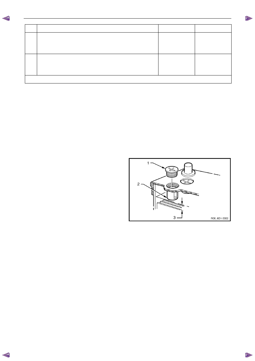
Remove each filler cap (1) and check the electrolyte
level is at the bottom of the filler-neck tube (2).
6
If the level is low, carefully add distilled water to the
cell until the level reaches the bottom of the filler-neck
tube.
N O T E
Do not overfill the cells, but maintain the level at
least 20 mm above the separator plates (3).
7
If the electrolyte usage seems excessive, check the
battery case is not faulty.
N O T E
Normal electrolyte usage is less than 30 ml per
10,000 kilometres (or slightly more for long,
continuous running or in high temperatures).
Figure 6D1-3 – 2
Battery
Page 6D1-3–9
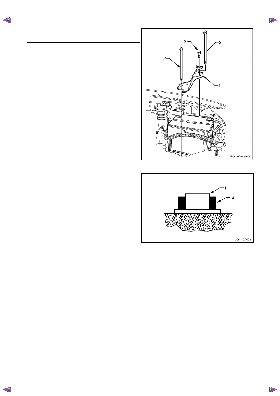
8
Ensure the battery hold-down bolts (2 & 3) and bracket
(1) firmly secure the battery.
Battery hold-down bolt
torque specification . . . . . . . . ...8.0 – 10.0 Nm
9
Check the cable insulation for damage or wear along
the cable. Replace the cable as required.
10
Check the cables do not have broken or frayed
strands and are secure in the terminals. Repair as
required.
Figure 6D1-3 – 3
11
Ensure the terminal clamp (2) sits below the top of the
battery post (1).
12
Check the terminal clamps are attached to the battery
posts securely. Replace the terminals as required.
13
Tighten the terminal clamp nuts to the correct torque
specification.
Battery terminal nut
torque specification . . . . . . . . . .2.0 – 5.0 Nm
14
Smear the battery posts and terminals with petroleum
jelly to resist corrosion.
Figure 6D1-3 – 4
3.3 Hydrometer
Test
As a lead-acid battery discharges, sulphur elements in the electrolyte move from the electrolyte solution into the lead
battery plates. This removes the sulphuric acid from the electrolyte and changes it to water. Therefore the concentration
of sulphuric acid in the electrolyte indicates the state of charge.
The concentration of sulphuric acid can be measured using a hydrometer. The state of charge is measured in terms of
specific gravity; the lower the specific gravity reading, the lower the state of charge.
N O T E
If distilled water has been added to the battery,
do not use the hydrometer until the battery has
been charged for at least 30 minutes.
1
Read and obey the safety precautions for working with batteries, refer to 2 Safety Precautions.
2
Remove the battery filler caps.
3
Force the air out of the hydrometer bulb.
4
Hold the hydrometer vertically in the cell with the pick-up tube submerged.
5
Draw in sufficient liquid to lift the hydrometer float freely when the bulb is fully released.
Battery
Page 6D1-3–10
6
Still holding the hydrometer vertically, record the reading.
7
Put the electrolyte back into the cell.
8
Repeat steps 3 to 7 for each cell.
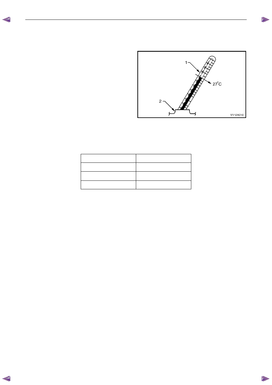
9
Determine the temperature of the battery by
temporarily placing a thermometer (1) into one of the
cells (2).
10
Install the battery filler caps.
11
Calculate the temperature-compensated readings: add
0.004 for every 5
°C above 27°C or subtract 0.004 for
every 5
°C below 27°C.
12
Determine the state of charge of the battery using the
temperature-compensated readings and the table
below.
N O T E
The specific gravity of a charged battery should
not vary more than 0.025 between cells. Larger
variations indicate defective cells and the battery
must be replaced, refer to 4.1 Battery.
Figure 6D1-3 – 5
Battery Condition
Specific Gravity Reading
Fully charged
1.240 to 1.260
Requires charging
<
1.190
Fully discharged
1.110 to 1.130
3.4 Load
Test
Load testing the battery with a high rate discharge (HRD) tester simulates using the starter motor and checks if the
battery is in serviceable condition. The battery must be at least 65% charged before commencing this test.
N O T E
HRD testers are available with either fixed or
variable loads. The operating procedures may
vary from brand to brand, therefore follow the
manufacturer’s instructions.
High Rate Discharge Load Test
1
Read and obey the safety precautions for working with batteries, refer to 2 Safety Precautions.
2
Ensure the state of the battery is at least 65% charged. Refer to 3.3
Hydrometer Test.
3
Refer to Warning, Caution and Notes in this section, before disconnecting the battery.
4
Disconnect the battery negative terminal.
5
Disconnect the battery positive terminal.
6
Connect the HRD tester to the battery terminals ensuring correct polarity.
7
Set the tester switches to suit the battery size.
Fixed load tester:
a
Apply the load for approximately 10 seconds to remove any surface charge.
b
Wait 15 seconds for the battery to recover.
Variable load tester:
a
Apply a 300 A load for approximately 15 seconds to remove any surface charge.
Battery
Page 6D1-3–11
b
Wait 15 seconds for the battery to recover.
8
If possible, set the selector to 50% of rapid discharge current (or three times the 20 hour discharge rate).
9
Apply the load test for 10 seconds and record the battery voltage. If one cell is faulty it will gas excessively or
overheat. This indicates a faulty battery.
10
Recharge the battery if the voltage is at or below the minimum voltage specified by the HRD manufacturer (or
9.6 V).
11
Replace the battery if the voltage is below the minimum voltage specified by the HRD manufacturer (or below 9.6 V
after the battery is charged and the test is repeated). Refer to 4.1 Battery.
12
Connect the battery positive terminal.
13
Connect the battery negative terminal.
Alternate Load Test
If HRD test equipment is not available, test the battery as follows:
1
Read and obey the safety precautions for working with batteries, refer to 2 Safety Precautions.
2
Ensure the state of the battery is at least 65% charged. Refer to 3.3
Hydrometer Test.
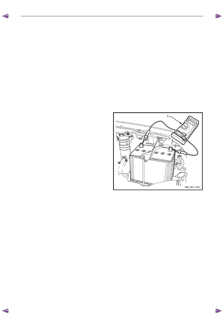
3
Connect a voltmeter (1) between the battery terminals.
4
Turn the headlights on to high-beam for 10 seconds to
remove any surface charge from the battery.
5
Remove fuses EB11 and EB12 from the engine
compartment fuse and relay housing. This prevents
vehicle ignition and fuel injection while cranking the
engine.
6
Crank the engine and read the voltmeter. At
temperatures above 5°C, the voltage of a fully charged
battery should not fall below 9.6 V.
N O T E
• If the battery and engine temperatures are
below 5
°C, the voltage may fall to 9 V.
• Try to avoid activating the starter motor
continuously for more than 30 seconds. If
activating the starter motor for 30 seconds,
allow the starter motor to cool for 3 minutes.
7
Replace the battery if a cell gasses excessively or
overheats or if the voltage falls away quickly.
Figure 6D1-3 – 6
3.5
Battery Current Draw Test
The following test determines if excess current is being drawn from the battery whilst the vehicle has all accessories
turned off. Excess current draw will cause the battery to go flat if the vehicle is not started for an extended period.
Test Preparation
1
Read and obey the safety precautions for working with batteries, refer to 2 Safety Precautions.
2
If the battery is flat, temporarily install a good battery for the duration of the test.
3
Ensure the vehicle starts and the accessories operate normally.
4
Ensure the theft deterrent system operates normally. Refer to 11A Immobiliser.
5
Open all the side windows for access purposes.
6
Switch the ignition off.
7
Check that all interior illumination is off, including any compartment lighting.
8
Close all doors.
Нет комментариевНе стесняйтесь поделиться с нами вашим ценным мнением.
Текст