Isuzu KB P190. Manual — part 913
Battery
Page 6D1-3–12
9
Lock the doors and activate the theft deterrent system to arm the vehicle.
10
If the multimeter contains fuses, check they are serviceable.
Test Procedure
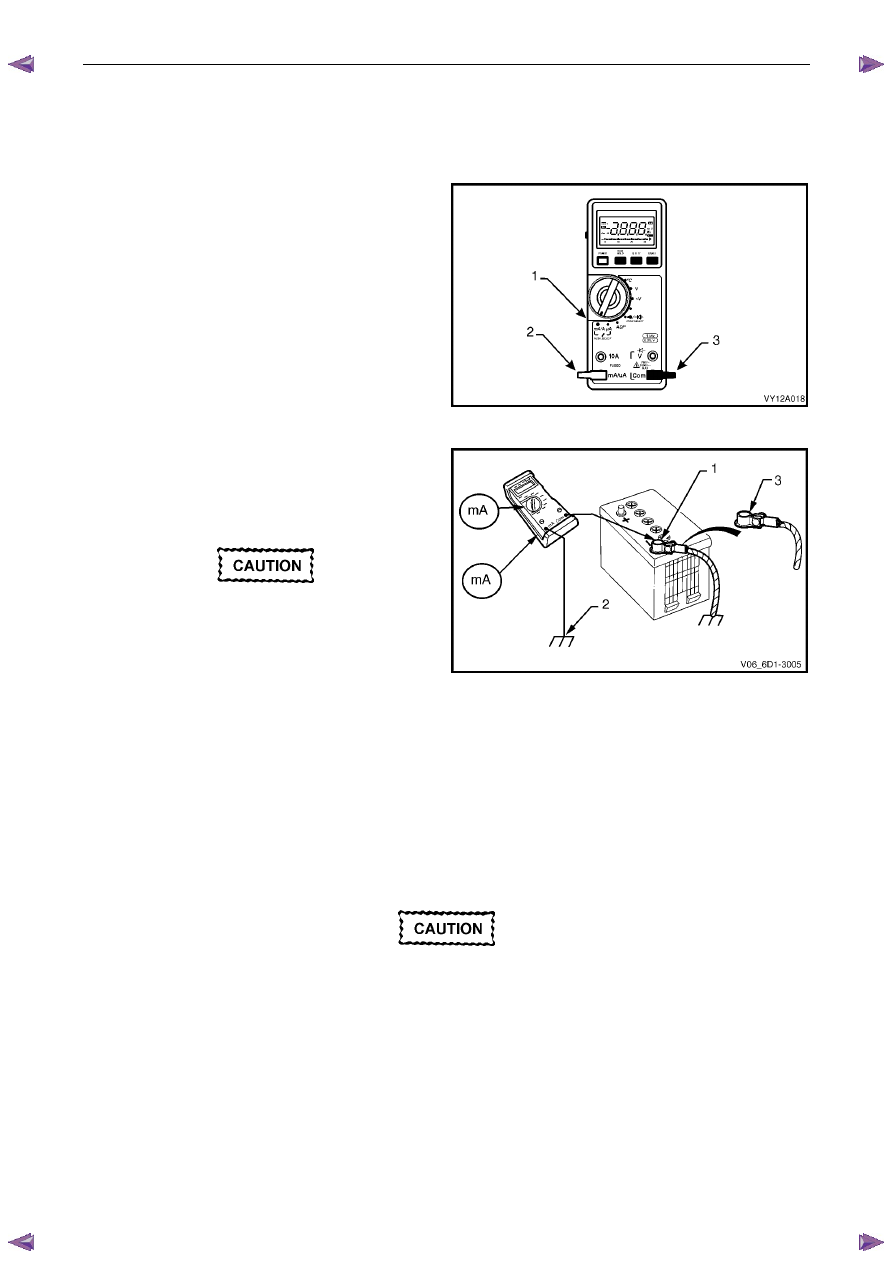
1
Switch the multimeter to the mA current range (1).
2
Connect the positive test lead (2) to the fused mA
terminal of the multimeter.
3
Connect the negative test (3) lead to the common
terminal of the multimeter.
4
Connect large alligator clips to the ends of both test
leads.
Figure 6D1-3 – 7
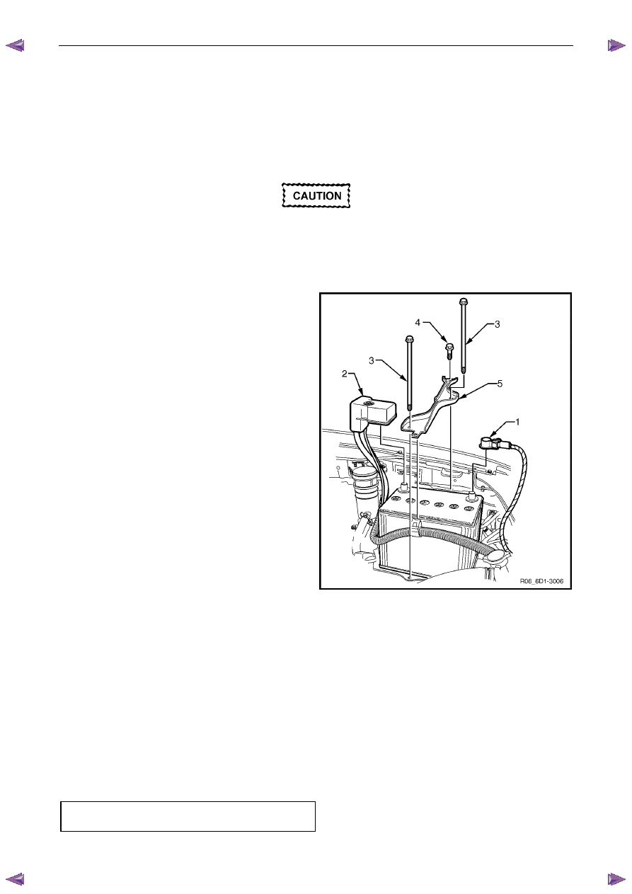
5
Connect the negative test lead clip to the threads of
the battery negative terminal clamp (1).
6
Connect the positive lead’s clip to the threads of a
convenient engine bolt (2).
Do not turn on the ignition switch while this
test is in progress. It will blow the
multimeter’s low current fuse.
7
Check the multimeter connections are secure.
8
Disconnect the vehicle’s main electrical earth by
removing the battery negative terminal cable retaining
nut (3) and separating the cable from the battery
clamp.
Figure 6D1-3 – 8
9
Read the vehicle’s battery saver current on the multimeter. The multimeter reading should be within 16 – 30 mA
(fluctuating).
10
If the multimeter reading is higher than specified, refer to Fault Diagnosis in this Section, otherwise restore the
vehicle to its prior condition, refer to Restore in this Section.
Fault Diagnosis
Do not open any doors during this inspection.
If the doors must be opened, reinstall the
battery terminal to the battery clamp to
protect the multimeter's fuse from blowing.
Alternatively, use the higher (10 A) fuse rated
terminal on the multimeter until the source of
the higher current draw has been found.
1
Visually inspect the vehicle for illuminated lamps and components activated by energised relays.
2
If the cause of the excessive current draw is not apparent, remove one fuse (or circuit breaker) at a time to
determine the circuit group that is drawing excess current. Refer to 8A Electrical Body & Chassis for fuse grouping
location.

Battery
Page 6D1-3–13
3
When the circuit group is determined, install the fuse / circuit breaker and identify the specific circuit within this
group that is drawing the excess current. Disconnect the wiring harness connectors in this circuit group one at a
time. Refer to 8A Electrical Body & Chassis.
4
When the cause is disconnected, the multimeter reading should drop to the correct reading as outlined in Step 9 of
the Test Procedure in this Section.
5
If required, remove the components in this circuit one at a time to determine the cause of the excessive standing
current. Refer to 8A Electrical Body & Chassis.
6
Repair the fault, refer to 8A Electrical Body & Chassis.
7
Ensure any fuses, circuit breakers and connectors that have been removed are secure.
Restore
1
Reconnect the electrical earth cable to the battery terminal and tighten the nut to the correct torque specification.
Battery terminal nut
torque specification . . . . . . . . . .2.0 – 5.0 Nm
2
Disconnect the multimeter connections.
Battery
Page 6D1-3–14
4 Service
Operations
4.1 Battery
Remove
Disconnection of the battery affects certain
vehicle electronic systems. Refer to 1.1
WARNING, CAUTION and NOTES before
disconnecting the battery.
1
Read and obey the safety precautions for working with batteries, refer to 2 Safety Precautions.
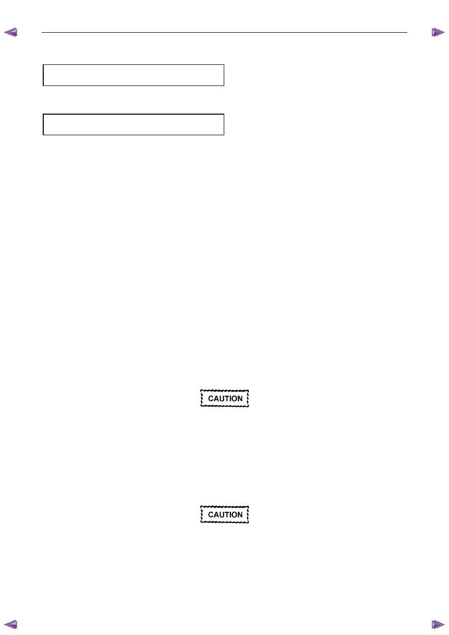
2
Disconnect the negative battery terminal (1).
3
Disconnect the positive battery terminal (2).
4
Remove the battery hold-down bolts (3 & 4) three
places, and the battery hold-down bracket (5).
5
Lift the battery out of the engine compartment.
Figure 6D1-3 – 9
Reinstall
N O T E
Before installing a used battery perform steps 1
to 10 of the battery inspection, refer to 3.2
Battery Inspection.
1
Ensure the battery tray, cables and terminals are clean and free from corrosion and moisture.
2
Ensure that no foreign objects such as loose nuts or stones are located in the battery tray.
3
Place the battery onto the battery tray and ensure the battery sits level.
4
Install the battery hold down bracket and tighten the bolt to the specified torque.
Battery hold-down bolt
torque specification . . . . . . . . ...8.0 – 10.0 Nm
Battery
Page 6D1-3–15
5
Install the positive terminal onto the positive battery post. Ensure the terminal sits below the top of the post and
tighten the terminal nut to the correct specification.
Battery terminal nut
torque specification . . . . . . . . . .2.0 – 5.0 Nm
6
Install the negative terminal onto the negative battery post. Ensure the terminal sits below the top of the post and
tighten the terminal nut to the correct specification.
Battery terminal nut
torque specification . . . . . . . . . .2.0 – 5.0 Nm
7
Smear the battery posts and cable terminals with petroleum jelly to inhibit corrosion.
4.2 Battery
Charge
Safety Precautions
Read and obey the general safety precautions for working with batteries, refer to 2
Safety Precautions.
The battery releases an explosive hydrogen and oxygen gas mixture during charging. Ensure there are no naked flames
or sparks near the battery.
Flat batteries can be safely boost-charged, however avoid excessive charging current if the battery is more than half
charged. Slow charging is best.
Fast charging can substantially boost a battery, but slow charging is required to fully charge the battery.
Do not use a fast charger:
•
for starting the vehicle,
•
if the specific gravity readings are not uniform between battery cells, refer to 3.3
Hydrometer Test,
•
if the specific gravity readings are above 1.20, refer to 3.3Hydrometer Test,
•
if the electrolyte is discoloured with brown sediment, and
•
if any of the above three conditions develop after beginning a fast charge.
Battery Charge Procedure
Disconnection of the battery affects certain
vehicle electronic systems. Refer to Warning,
Caution and Notes in this section before
disconnecting the battery.
1
Perform steps 1 to 10 of the battery inspection, refer to 3.2
Battery Inspection.
2
Remove the battery from the vehicle. Refer to 4.1
Battery.
3
If required remove the battery filler caps. Let the caps rest loosely on top of the filler tubes.
Always ensure the connections are to the
correct polarity and follow the manufacturer’s
recommendations for battery charging.
4
Connect the battery to the battery charger.
5
Set the charging current using the following table as a guide.
Нет комментариевНе стесняйтесь поделиться с нами вашим ценным мнением.
Текст