Nissan GT-R (2007-2014 year). PARKING BRAKE SYSTEM / REAR AXLE. Service Manual
PB-1
BRAKES
C
D
E
G
H
I
J
K
L
M
SECTION
PB
A
B
PB
N
O
P
CONTENTS
PARKING BRAKE SYSTEM
PRECAUTION . . . . . . . . . . . ...
PRECAUTIONS . . . . . . . . . . . . ...
Precaution for Working Range at a Regular Deal-
ership . . . . . . . . . . . . . . . . . ....
General Precautions . . . . . . . . . . . .....
PREPARATION . . . . . . . . . . .
PREPARATION . . . . . . . . . . . . ...
Commercial Service Tool . . . . . . . . . . ..
PERIODIC MAINTENANCE . . . . . . ..
PARKING BRAKE SYSTEM . . . . . . . ...
Inspection and Adjustment . . . . . . . . . ....
REMOVAL AND INSTALLATION . . . .
PARKING BRAKE SHOE . . . . . . . . ..
Exploded View . . . . . . . . . . . . . . ..
Inspection and Adjustment . . . . . . . . . ...
SERVICE DATA AND SPECIFICATIONS
(SDS) . . . . . . . . . . . . . . . .
SERVICE DATA AND SPECIFICATIONS
(SDS) . . . . . . . . . . . . . . . . ..
Parking Drum Brake . . . . . . . . . . . . .
Parking Brake Control . . . . . . . . . . . ..
Revision: 2012 November
2014 GT-R
PB-2
< PRECAUTION >
PRECAUTIONS
PRECAUTION
PRECAUTIONS
Precaution for Working Range at a Regular Dealership
INFOID:0000000009167682
CAUTION:
The service items unmentioned on this manual are recommended to be performed by a GT-R certified
NISSAN dealer. Because those service items require special equipment and a GT-R certified technical
staff who completed special training.
General Precautions
INFOID:0000000009159888
CAUTION:
After finishing servicing, check that all the tools and waste are stored in a customary place.
Revision: 2012 November
2014 GT-R
PREPARATION
PB-3
< PREPARATION >
C
D
E
G
H
I
J
K
L
M
A
B
PB
N
O
P
PREPARATION
PREPARATION
Commercial Service Tool
INFOID:0000000009159889
Tool name
Description
Power tool
Loosening bolts and nuts
PBIC0190E
Revision: 2012 November
2014 GT-R

PB-4
< PERIODIC MAINTENANCE >
PARKING BRAKE SYSTEM
PERIODIC MAINTENANCE
PARKING BRAKE SYSTEM
Inspection and Adjustment
INFOID:0000000009159890
INSPECTION
Parking Brake Lever Stroke
1.
Operate the parking brake lever with a force of 196 N (20 kg, 44 lb). Check that the lever stroke is within
the specified number of notches. (Check it by listening to the clicks of the ratchet.)
2.
When brake warning lamp turns ON, check that the lever stroke is within the specified number of notches.
(Check it by listening to the clicks of the ratchet.)
Inspect Components
• Check each component for installation condition such as looseness.
• Check the parking brake lever assembly for bend, damage and cracks. Replace if necessary.
• Check the cables and equalizer for wear, damage and cracks. Replace if necessary.
• Check the parking brake switch, and replace it if necessary. (This work is recommended to be performed by
GT-R certified NISSAN dealer.)
ADJUSTMENT
1.
Remove tires with power tool. Refer to
.
2.
Fix the disc rotor using wheel nuts.
3.
Remove the instrument garnish. Refer to
.
4.
Remove the console finisher assembly. Refer to
5.
Remove the cup holder finisher. Refer to
.
6.
Rotate the adjusting nut (1) and loosen the cable, and then
return the parking brake lever.
7.
Remove the adjusting hole plug from the disc rotor. Turn the
adjuster (1) in the direction (A) as shown in the figure using a
suitable tool until the disc rotor is locked.
8.
Turn back the adjuster 5 or 6 notches from the locked position.
9.
Rotate the disc rotor to check that there is no drag. Install the
adjusting hole plug. If there is any drag, refer to
.
10. Adjust the cable with the following procedure.
a.
Operate the parking brake lever with a force of 294 N (30 kg, 66
lb) for 10 strokes or more.
b.
Adjust the parking brake lever stroke by turning the adjusting
nut.
CAUTION:
Never reuse the adjusting nut if the adjusting nut removed.
Number of notches
: Refer to
Number of notches
: Refer to
NNFIB0001ZZ
JPFIB0002ZZ
Revision: 2012 November
2014 GT-R
PARKING BRAKE SYSTEM
PB-5
< PERIODIC MAINTENANCE >
C
D
E
G
H
I
J
K
L
M
A
B
PB
N
O
P
c.
Operate the parking brake lever with a force of 196 N (20 kg, 44 lb). Check that the lever stroke is within
the specified number of notches. (Check it by listening to the clicks of the ratchet.)
d.
Rotate the disc rotor with the parking brake lever released and check that there is no drag. Refer to
.
Number of notches
: Refer to
Revision: 2012 November
2014 GT-R
PB-6
< REMOVAL AND INSTALLATION >
PARKING BRAKE SHOE
REMOVAL AND INSTALLATION
PARKING BRAKE SHOE
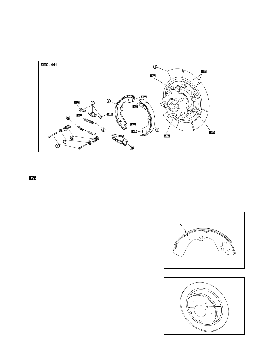
Exploded View
INFOID:0000000009159895
Inspection and Adjustment
INFOID:0000000009159897
INSPECTION AFTER REMOVAL
Lining Thickness Inspection
Check thickness (A) of lining.
Drum Inner Diameter Inspection
Check inner diameter (B) of drum.
1.
Back plate
2.
Parking brake shoe
3.
Adjuster
4.
Adjuster spring
5.
Return spring
6.
Anti-rattle spring
7.
Retainer
8.
Anti-rattle pin
9.
Toggle lever
: Apply PBC (Poly Butyl Cuprysil) grease or silicone-based grease.
NNFIB0005ZZ
A
: Refer to
.
SBR021A
B
: Refer to
.
JPFIB0008ZZ
Revision: 2012 November
2014 GT-R
PARKING BRAKE SHOE
PB-7
< REMOVAL AND INSTALLATION >
C
D
E
G
H
I
J
K
L
M
A
B
PB
N
O
P
Other Inspections
Check the following items, and replace the parts if necessary.
• Lining for excessive wear, damage or peeling.
• Brake shoe sliding surface for excessive wear or damage.
• Anti-rattle pin and retainer for excessive wear, damage or rust.
• Adjuster spring, return spring and anti-rattle spring for settling, excessive wear, damage or rust.
• Adjuster for smoothness.
• Toggle lever for excessive wear, damage or rust.
• Visually check inside of the drum for excessive wear, cracks or damage with a pair of vernier calipers.
ADJUSTMENT AFTER INSTALLATION
Check the parking brake for drag. Perform the following procedure if necessary.
1.
Adjust the parking brake lever stroke. Refer to
PB-4, "Inspection and Adjustment"
.
2.
Check the parking brake for drag again. Check the rear disc brake for drag if necessary. (This work is rec-
ommended to be performed by GT-R certified NISSAN dealer.)
Revision: 2012 November
2014 GT-R

PB-8
< SERVICE DATA AND SPECIFICATIONS (SDS)
SERVICE DATA AND SPECIFICATIONS (SDS)
SERVICE DATA AND SPECIFICATIONS (SDS)
SERVICE DATA AND SPECIFICATIONS (SDS)
Parking Drum Brake
INFOID:0000000009159898
Unit: mm (in.)
Parking Brake Control
INFOID:0000000009159899
Item
Limit
Brake lining
1.5 (0.059)
Drum (disc of inner diameter)
191 (7.52)
Item
Standard
Number of notches [under force of 196 N (20 kg, 44 lb)]
5 – 6 notches
Number of notches when brake warning lamp turns ON
1 notch
Revision: 2012 November
2014 GT-R
RAX-1
TRANSMISSION & DRIVELINE
C
E
F
G
H
I
J
K
L
M
SECTION
RAX
A
B
RAX
N
O
P
CONTENTS
REAR AXLE
SYMPTOM DIAGNOSIS . . . . . . . ...
NOISE, VIBRATION AND HARSHNESS
(NVH) TROUBLESHOOTING . . . . . . . .
NVH Troubleshooting Chart . . . . . . . . . ..
PRECAUTION . . . . . . . . . . . ...
PRECAUTIONS . . . . . . . . . . . . ...
Precaution for Working Range at a Regular Deal-
ership . . . . . . . . . . . . . . . . . ....
General Precautions . . . . . . . . . . . . .
PERIODIC MAINTENANCE . . . . . . .
REAR WHEEL HUB AND HOUSING . . . .
Inspection . . . . . . . . . . . . . . . . .
REAR DRIVE SHAFT . . . . . . . . . . .
Inspection . . . . . . . . . . . . . . . . .
REMOVAL AND INSTALLATION . . . .
REAR WHEEL HUB AND HOUSING . . . .
Exploded View . . . . . . . . . . . . . . ..
Revision: 2012 November
2014 GT-R
RAX-2
< SYMPTOM DIAGNOSIS >
NOISE, VIBRATION AND HARSHNESS (NVH) TROUBLESHOOTING
SYMPTOM DIAGNOSIS
NOISE, VIBRATION AND HARSHNESS (NVH) TROUBLESHOOTING
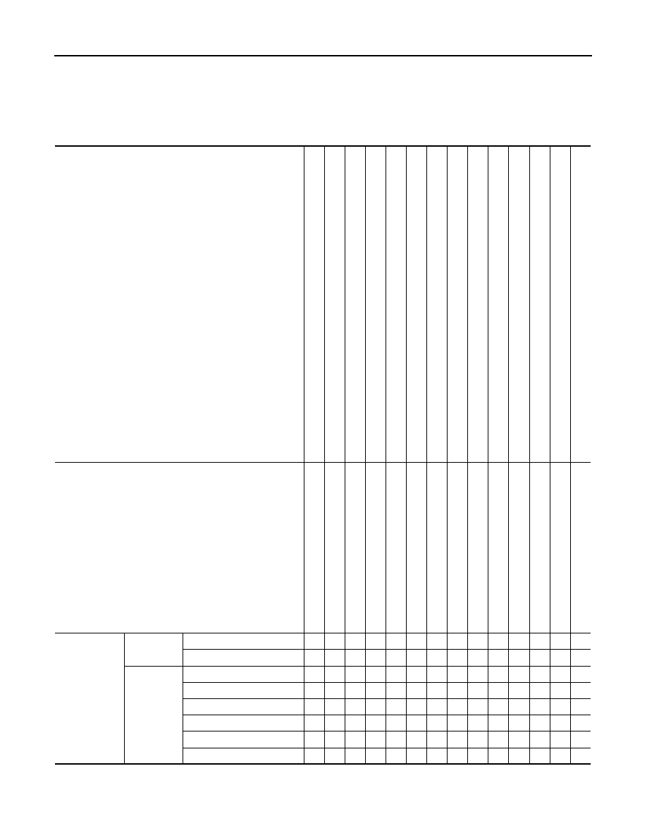
NVH Troubleshooting Chart
INFOID:0000000009163173
Use chart below to find the cause of the symptom. If necessary, repair or replace these parts.
×
: Applicable
Reference
—
T
h
is
wo
rk i
s
rec
o
m
m
e
n
d
e
d
to
be
p
e
rfo
rme
d
by
G
T
-R ce
rti
fie
d NIS
SAN d
eal
er
.
—
T
h
is
wo
rk i
s
rec
o
m
m
e
n
d
e
d
to
be
p
e
rfo
rme
d
by
G
T
-R ce
rti
fie
d NIS
SAN d
eal
er
.
—
NVH in DLN
section.
NVH in DLN
section.
NVH
in
RAX and RSU sections.
Re
fe
r to
REAR AXL
E i
n
t
h
is cha
rt.
NVH in WT
section.
NVH in WT
section.
Re
fe
r to
DRIVE SHA
FT i
n
t
h
is cha
rt.
NVH in BR
section.
NVH in ST
section.
Possible cause and SUSPECTED PARTS
Ex
ce
ss
iv
e joi
nt an
gle
Jo
in
t sl
id
in
g
re
si
st
a
n
c
e
Im
ba
la
nc
e
Imp
rop
er i
ns
ta
lla
ti
o
n,
lo
os
en
es
s
Part
s int
e
rference
PROPELLER S
H
A
F
T
DIFF
ERENTIAL
REAR AX
LE A
N
D
REAR SUSPE
N
S
ION
REAR AX
LE
TIRE
ROAD WHEEL
DRIVE SHAFT
BRAKE
STE
E
RING
Symptom
DRIVE
SHAFT
Noise
×
×
×
×
×
×
×
×
×
×
Shake
×
×
×
×
×
×
×
×
×
REAR AXLE
Noise
×
×
×
×
×
×
×
×
×
×
Shake
×
×
×
×
×
×
×
×
×
Vibration
×
×
×
×
×
×
×
Shimmy
×
×
×
×
×
×
×
Judder
×
×
×
×
×
×
Poor quality ride or handling
×
×
×
×
×
Revision: 2012 November
2014 GT-R
PRECAUTIONS
RAX-3
< PRECAUTION >
C
E
F
G
H
I
J
K
L
M
A
B
RAX
N
O
P
PRECAUTION
PRECAUTIONS
Precaution for Working Range at a Regular Dealership
INFOID:0000000009188290
CAUTION:
The service items unmentioned on this manual are recommended to be performed by a GT-R certified
NISSAN dealer. Because those service items require special equipment and a GT-R certified technical
staff who completed special training.
Precaution for Supplemental Restraint System (SRS) "AIR BAG" and "SEAT BELT
PRE-TENSIONER"
INFOID:0000000009163174
The Supplemental Restraint System such as “AIR BAG” and “SEAT BELT PRE-TENSIONER”, used along
with a front seat belt, helps to reduce the risk or severity of injury to the driver and front passenger for certain
types of collision. This system includes seat belt switch inputs and dual stage front air bag modules. The SRS
system uses the seat belt switches to determine the front air bag deployment, and may only deploy one front
air bag, depending on the severity of a collision and whether the front occupants are belted or unbelted.
Information necessary to service the system safely is included in the “SRS AIR BAG” and “SEAT BELT” of this
Service Manual.
WARNING:
Always observe the following items for preventing accidental activation.
• To avoid rendering the SRS inoperative, which could increase the risk of personal injury or death in
the event of a collision that would result in air bag inflation, all maintenance must be performed by
an authorized NISSAN/INFINITI dealer.
• Improper maintenance, including incorrect removal and installation of the SRS, can lead to personal
injury caused by unintentional activation of the system. For removal of Spiral Cable and Air Bag
Module, see “SRS AIR BAG”.
• Never use electrical test equipment on any circuit related to the SRS unless instructed to in this Ser-
vice Manual. SRS wiring harnesses can be identified by yellow and/or orange harnesses or harness
connectors.
PRECAUTIONS WHEN USING POWER TOOLS (AIR OR ELECTRIC) AND HAMMERS
WARNING:
Always observe the following items for preventing accidental activation.
• When working near the Air Bag Diagnosis Sensor Unit or other Air Bag System sensors with the
ignition ON or engine running, never use air or electric power tools or strike near the sensor(s) with
a hammer. Heavy vibration could activate the sensor(s) and deploy the air bag(s), possibly causing
serious injury.
• When using air or electric power tools or hammers, always switch the ignition OFF, disconnect the
battery, and wait at least 3 minutes before performing any service.
General Precautions
INFOID:0000000009163175
CAUTION:
After finishing servicing, check that all the tools and waste are stored in a customary place.
Revision: 2012 November
2014 GT-R
RAX-4
< PERIODIC MAINTENANCE >
REAR WHEEL HUB AND HOUSING
PERIODIC MAINTENANCE
REAR WHEEL HUB AND HOUSING
Inspection
INFOID:0000000009163180
MOUNTING INSPECTION
Check the mounting conditions (looseness, back lash) of each component and component conditions (wear,
damage) are normal.
WHEEL BEARING INSPECTION
• Move wheel hub and bearing assembly in the axial direction by hand. Check there is no looseness of wheel
bearing.
• Rotate wheel hub, and check that is no unusual noise or other irregular conditions. If there is any of abnor-
mal conditions, replace wheel hub and bearing assembly.
Axial end play
: 0.05 mm (0.002 in) or less
Revision: 2012 November
2014 GT-R
REAR DRIVE SHAFT
RAX-5
< PERIODIC MAINTENANCE >
C
E
F
G
H
I
J
K
L
M
A
B
RAX
N
O
P
REAR DRIVE SHAFT
Inspection
INFOID:0000000009163181
• Check drive shaft mounting point and joint for looseness and other damage.
• Check boot for cracks and other damage.
CAUTION:
Replace entire drive shaft assembly when noise or vibration occurs from drive shaft.
Revision: 2012 November
2014 GT-R
RAX-6
< REMOVAL AND INSTALLATION >
REAR WHEEL HUB AND HOUSING
REMOVAL AND INSTALLATION
REAR WHEEL HUB AND HOUSING
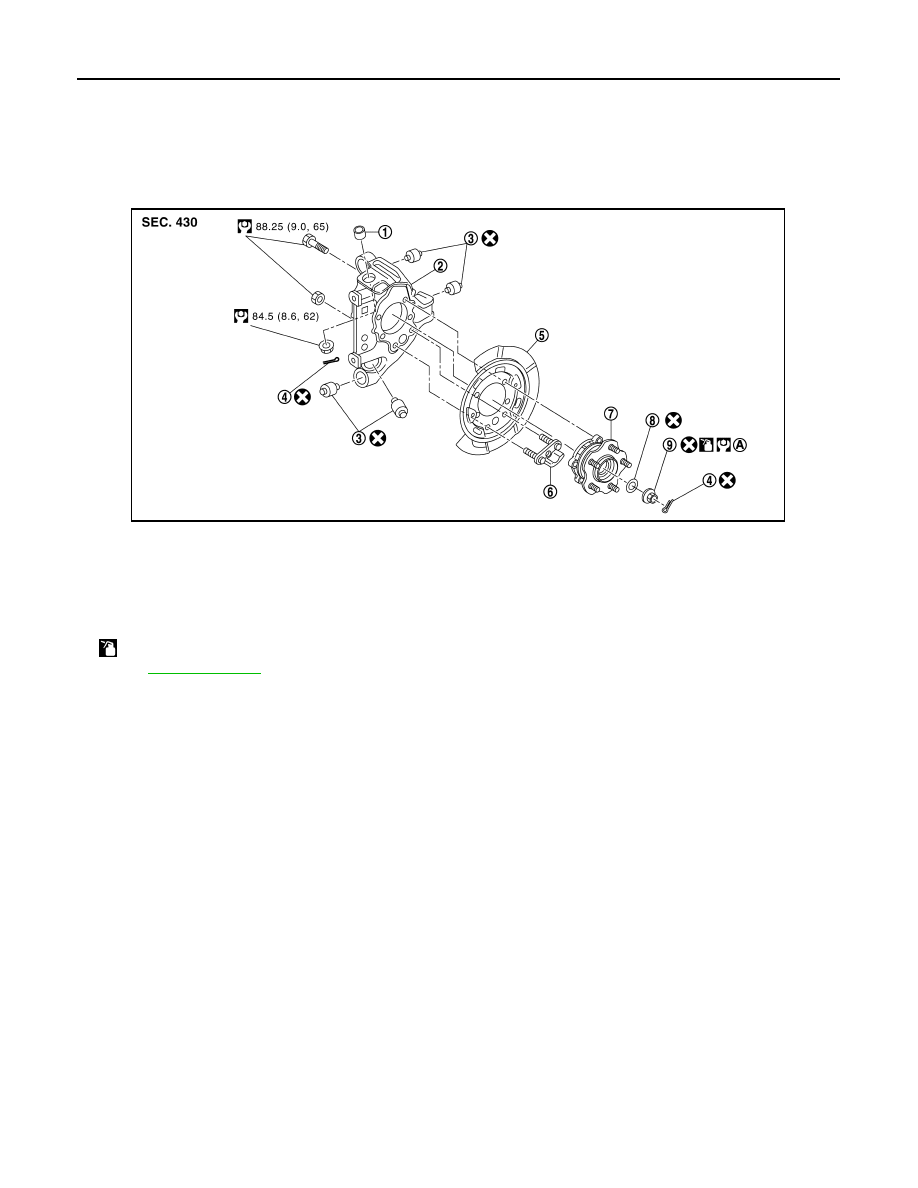
Exploded View
INFOID:0000000009163182
1.
Ball seat
2.
Axle housing
3.
Bushing
4.
Cotter pin
5.
Back plate
6.
Anchor block
7.
Wheel hub and bearing assembly
8.
Spring washer
9.
Wheel hub lock nut
A.
When tightening wheel hub lock nut, tighten the lock nut to 225 N·m (23 kg-m, 166 ft-lb), loosen it, and retighten it to 350 N·m
(36 kg-m, 258 ft-lb) to break in spring washer and the contact surface of wheel hub assembly.
: Apply anti-corrosion oil.
Refer to
for the symbols in the figure.
JSDIA3974GB
Revision: 2012 November
2014 GT-R
Нет комментариевНе стесняйтесь поделиться с нами вашим ценным мнением.
Текст