Freightliner Cargo Maintenance Manual — part 15
33–01 Knuckle Pin Lubrication
Hold a pressure gun on each fitting until fresh grease
appears. See
. This will ensure that all the old
contaminated grease has been forced out. It is not
necessary to exceed 4000 psi (27 560 kPa). The
best distribution of new lubricant and the best purg-
ing of old lubricant occurs when about 4000 psi (27
560 kPa) pressure is applied at the grease gun
nozzle. Using a 40 to 1 booster, the air should be
limited to 100 psi (689 kPa); using a 50 to 1 booster,
the air should be limited to 80 psi (551 kPa). Higher
or lower pressures are not recommended.
When lubricating knuckle pin bushings for initial
maintenance, raise the front axle until the front tires
are off the ground. Wipe the lube fittings clean, and
slowly feed multipurpose chassis grease (NLGI grade
1 or 2) into each bushing area while turning the
wheels from extreme right to left and back again
(lock to lock). This will eliminate small air pockets
and improve grease distribution.
Lower the tires to the ground, and regrease both top
and bottom bushings until new grease is seen at the
seal on the bushing opposite the fittings. The grease
seal will accept the grease pressure without damag-
ing the seal, and is designed to have grease pumped
out through it during lubrication. Even if grease leaks
out around the top or bottom plate gasket, continue
pumping until new grease is seen at the seal on the
bushing opposite the grease fitting.
When lubricating knuckle pin bushings at M1 through
M5, do not raise the front axle. Wipe the lube fittings
clean, and apply multipurpose chassis grease until
new grease is seen at the grease seal on the bush-
ing opposite the fittings. The grease seal will accept
the grease pressure without damaging the seal, and
is designed to have grease pumped out through it
during lubrication. Even if grease leaks out around
the top or bottom plate gasket, continue pumping
until new grease is seen at the seal on the bushing
opposite the grease fitting.
33–02 Tie-Rod End Inspection
1.
Shake the cross-tube. Movement or looseness
between the tapered shaft of the ball and the
cross-tube socket members means that the tie-
rod end assembly must be replaced.
2.
The threaded portion of the tie-rod end assembly
must be inserted all the way into the cross-tube
split, for adequate clamping. See
. Replace
the parts if this cannot be done. For instructions,
see the axle manufacturer’s service manual.
3.
Check the tie-rod end nut and clamp nut torques.
Tighten the tie-rod end nut 100 lbf·ft (136 N·m),
and tighten the clamp nut 40 to 55 lbf·ft (54 to 75
N·m).
33–03 Tie-Rod End Lubrication
Wipe the tie-rod end grease fittings clean, then pump
multipurpose chassis grease (NLGI grade 1 or 2) to
the tie-rod ends until all used grease is forced out
and new grease appears at the ball stud neck.
33–04 All-Axle Alignment
Checking
Drive Axle Alignment Checking
Check the axle alignment, parallelism, and thrust
angle measurements for the rear drive axles. Use the
applicable procedure and specifications in Group 35
of the
Cargo Workshop Manual
.
f320032a
1
1
A
10/20/93
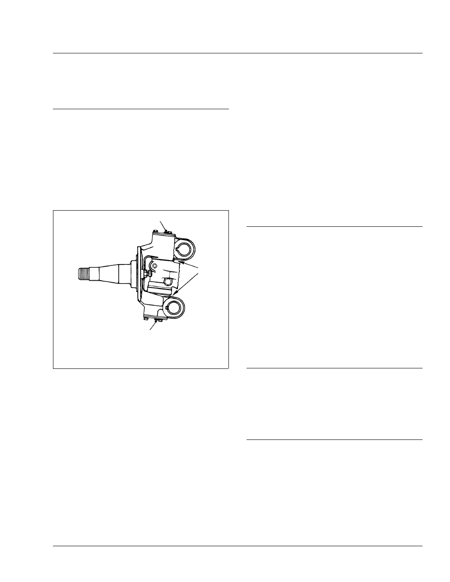
A. Pump lubricant into each grease fitting until fresh
grease comes out here.
1.
Grease Fitting
Fig. 1, Meritor Front Axle
Front Axle
33
Cargo Maintenance Manual, June 2001
33/1

Front Axle Toe-in Checking
For vehicle alignment to be accurate, the shop floor
must be level in every direction. The turn plates for
the front wheels must rotate freely without friction,
and the alignment equipment must be calibrated ev-
ery three months by a qualified technician from the
equipment manufacturer. Freightliner dealers must
have proof of this calibration history.
1.
Apply the parking brakes and chock the rear
tires.
2.
Raise the front of the vehicle until the tires clear
the ground. Check that the safety stands will
support the combined weight of the cab, axle,
and frame. Place safety stands under the axle.
3.
Using spray paint or a piece of chalk, mark the
entire center rib of each front tire.
4.
Place a scribe or pointed instrument against the
marked center rib of each tire, and turn the tires.
The scribe must be held firmly in place so that a
single straight line is scribed all the way around
each front tire.
5.
Place a turn-plate or turntable under both front
tires. Raise the front of the vehicle, remove the
safety stands from under the axle, then lower the
vehicle. Remove the lock-pins from the gauges;
make sure the tires are exactly straight ahead.
NOTE: If turn-plates or turntables are not avail-
able, lower the vehicle. Remove the chocks
from the rear tires and release the parking
brakes. Move the vehicle backward and then
forward about six feet (two meters).
6.
Place a trammel bar at the rear of the front tires;
locate the trammel pointers at spindle height,
and adjust the pointers to line up with the scribe
lines on the center ribs of the front tires. See
. Lock in place. Check that the scale is set
on zero.
7.
Move the trammel bar to the front of the tires (
), and adjust the scale end so that the
pointers line up with the scribe lines. See
8.
Read the toe-in from the scale, and compare it to
the toe-in specification in Group 33 of the
Cargo
Workshop Manual
. If corrections are needed, see
Group 33 of the
Cargo Workshop Manual
for
instructions on adjusting the toe-in.
f320033a
1
10/20/93
OK
OK
NOTE: Pinch bolt not shown to provide clarity.
1.
Cross-Tube Split
Fig. 2, Tie-Rod End Adjustment
A
B
f330082a
08/29/94
NOTE: B minus A equals toe-in.
Fig. 3, Wheel Toe-In (Overhead View)
Front Axle
33
Cargo Maintenance Manual, June 2001
33/2
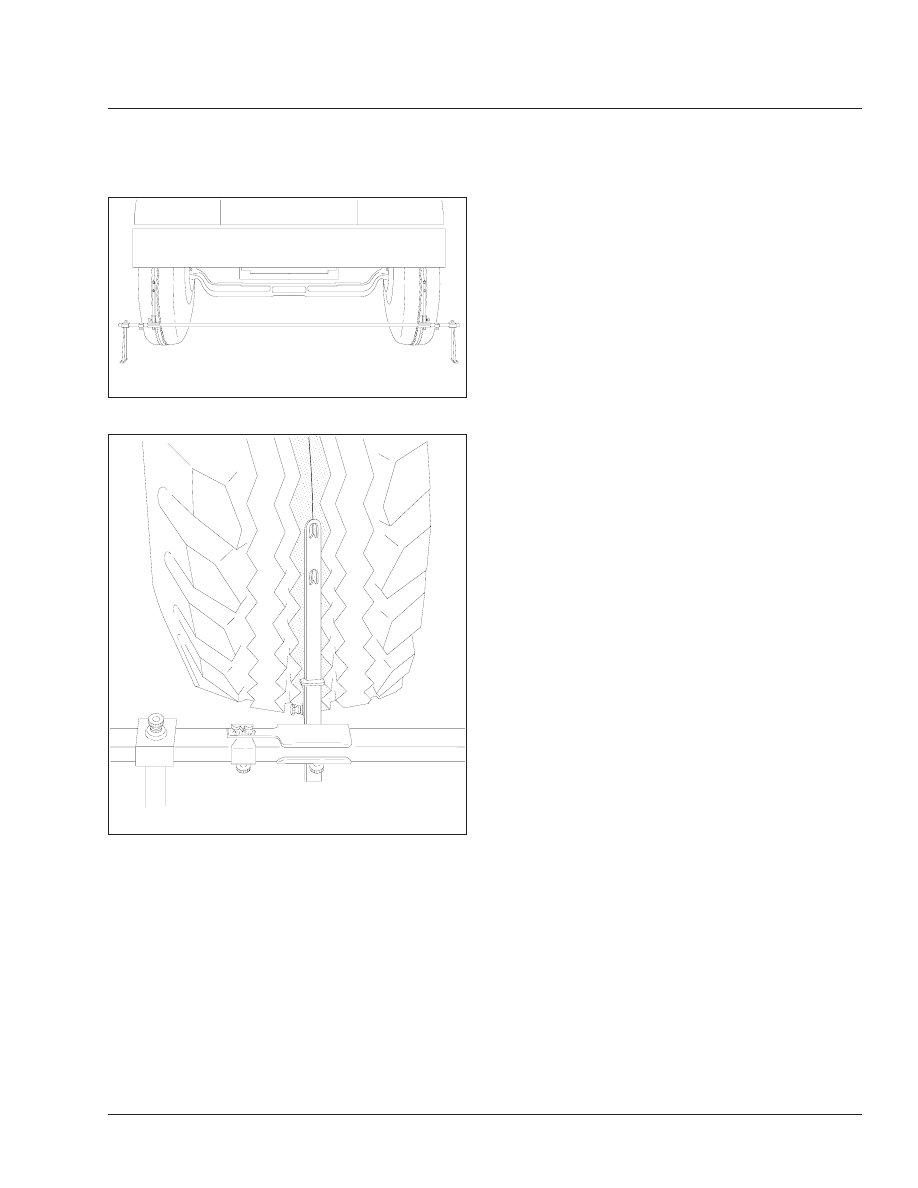
f330014a
08/30/94
Fig. 4, Trammel Bar Positioning
f400100a
08/30/94
Fig. 5, Setting the Trammel Bar Pointers
Front Axle
33
Cargo Maintenance Manual, June 2001
33/3
Title of Maintenance Operation (MOP)
MOP Number
Axle Breather Check . . . . . . . . . . . . . . . . . . . . . . . . . . . . . . . . . . . . . . . . . . . . . . . . . . . . . . . . . . . . . . . 35–02
Axle Lubricant Change and Magnetic Plug Clean . . . . . . . . . . . . . . . . . . . . . . . . . . . . . . . . . . . . . . . . . . 35–03
Axle Lubricant Level Check . . . . . . . . . . . . . . . . . . . . . . . . . . . . . . . . . . . . . . . . . . . . . . . . . . . . . . . . . . 35–01
Rear Axle
35
Index, Alphabetical
Cargo Maintenance Manual, January 2000
Нет комментариевНе стесняйтесь поделиться с нами вашим ценным мнением.
Текст