Suzuki Grand Vitara JB627. Manual — part 158
3C-36 Transfer:
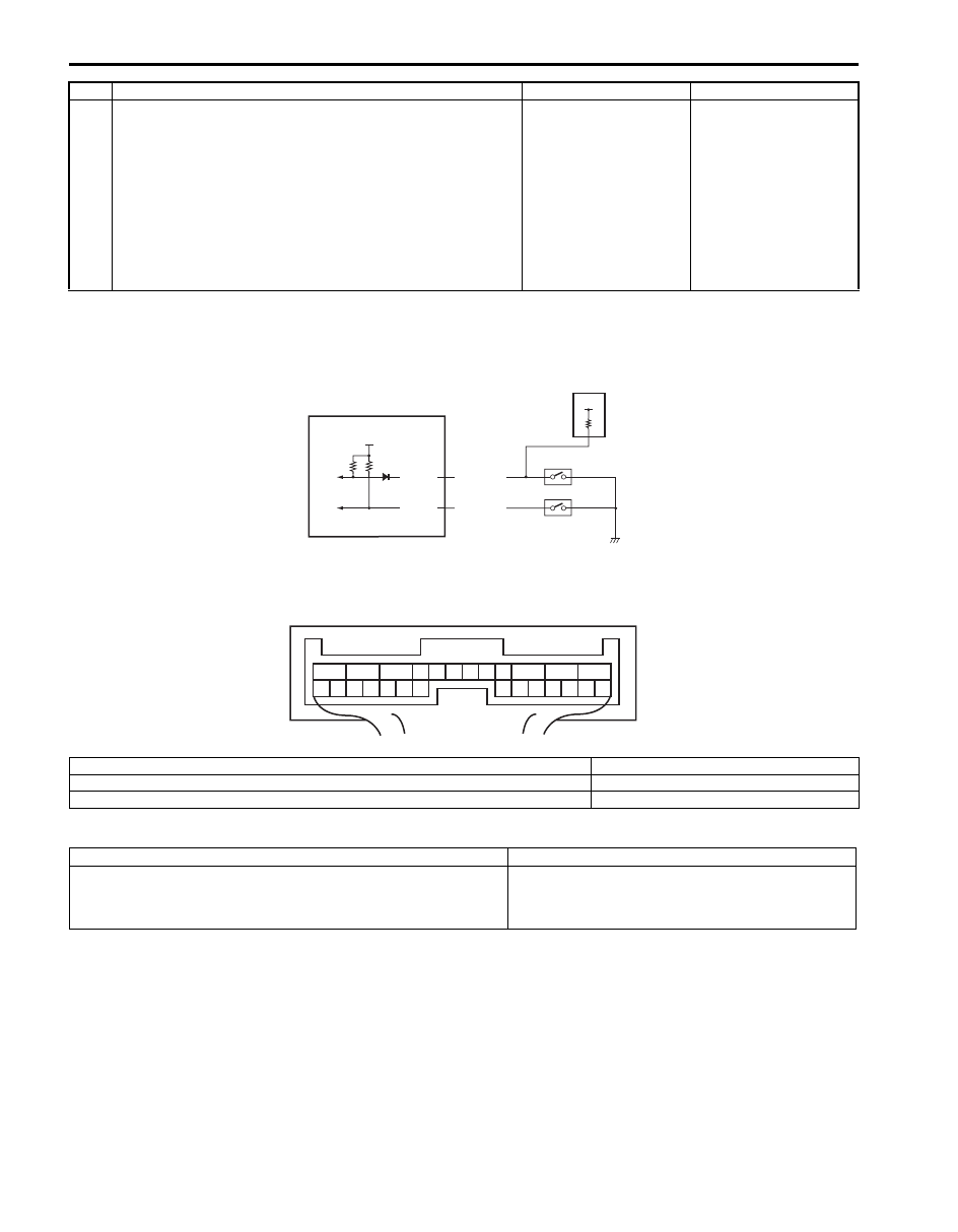
DTC C1228: 4L/N Switch Circuit Short
S6JB0B3304019
Wiring Diagram
DTC Detecting Condition and Trouble Area
4
Wire harness check
1) Disconnect connector from 4WD control module
connector “E91” with ignition switch OFF.
2) Check for proper connection to “E91-13” terminal of
4WD control module connector.
3) If OK, measure resistance between “PNK/WHT” terminal
of 4L/N switch connector and “E91-13” terminal of 4WD
control module connector.
Is it 1
Ω
or less?
Substitute a known-
good 4WD control
module and recheck.
“PNK/WHT” wire is
open or high resistance.
Step
Action
Yes
No
IG
E91-13
E91-14
RED/GRN
PNK/WHT
2
3
4
12V
1
1
2
3
4
5
6
7
8
9
10
11
12
13
14
15
16
17
18
19
20
21
22
23
24
25
26
[A]
I5JB0A332018-01
[A]: 4WD control module connector “E91” (viewed from harness side)
3. 4L/N switch
1. 4WD control module
4. Center differential lock switch
2. TCM
DTC detecting condition
Trouble area
Though transfer shift actuator motor position switch is “4L-lock”
position, the OFF signal is not input from the 4L/N switch.
• 4L/N switch
• 4L/N switch circuit
• 4WD control module

Transfer: 3C-37
DTC Confirmation Procedure
1) Clear DTC using scan tool.
2) Select transfer switch to “4L-lock” position and keep its position for 1 min.
3) Check DTC.
Troubleshooting
Step
Action
Yes
No
1
Was “4WD control system check” performed?
Go to Step 2.
Go to “4WD Control
System Check”.
2
4L/N switch circuit check
1) Disconnect 4L/N switch connector with ignition switch
OFF.
2) Check for proper connection to terminal of 4L/N switch
connector.
3) If connection is OK, measure voltage between “PNK/
WHT” terminal of 4L/N switch connector and vehicle
body ground with ignition switch ON.
Is it 10 – 14 V?
Go to Step 3.
Go to Step 4.
3
4L/N switch check
1) Check 4L/N switch referring to “Transfer Assembly
Is switch in good condition?
Substitute a known-
good 4WD control
module and recheck.
Replace 4L/N switch.
4
Wire harness check
1) Disconnect connector from 4WD control module
connector “E91” with ignition switch OFF.
2) Check for proper connection to “E91-13” terminal of
4WD control module connector.
3) If OK, measure resistance between “PNK/WHT” terminal
of 4L/N switch connector and “E91-13” terminal of 4WD
control module connector.
Is it 1 M
Ω
or more?
Substitute a known-
good 4WD control
module and recheck.
“PNK/WHT” wire is
shorted to ground
circuit.
3C-38 Transfer:
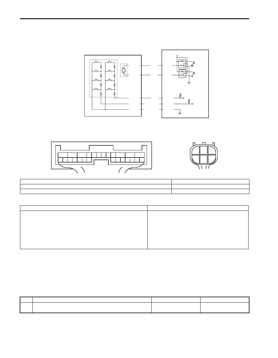
DTC C1230: Transfer Actuator Circuit Malfunction
S6JB0B3304020
Wiring Diagram
DTC Detecting Condition and Trouble Area
DTC Confirmation Procedure
1) Clear DTC using scan tool.
2) Select transfer switch to “4H” position and keep its position for 10 seconds. Similarly select transfer switch to “4H-
lock”, “N” and “4L-lock” position.
3) Check DTC.
Troubleshooting
5V
12V
E91-2
5V
YEL
RED/BLK
BLU
M
E91-3
E91-25
E91-26
RED
E91-24
BLK/YEL
1
2
3
C54-1
C54-4
C54-2
C54-3
C54-5
4
1
2
3
4
5
6
7
8
9
10
11
12
13
14
15
16
17
18
19
20
21
22
23
24
25
26
[A]
1
2
3
4
5
6
[B]
I5JB0A332017-01
[A]: 4WD control module connector “E91” (viewed from harness side)
2. Transfer shift actuator motor position switch
[B]: Transfer shift actuator connector “C54” (engine harness side) (viewed from harness side)
3. Transfer shift actuator motor
1. Transfer shift actuator
4. 4WD control module
DTC detecting condition
Trouble area
• Position switch in transfer shift actuator is not changed for 3
seconds even if command signal of motor relay for transfer
shift actuator (included in 4WD control module) is turned on.
or
• Monitor signal from motor relay of transfer shift actuator
(included in 4WD control module) is inconsistent with
command signal to motor relay of transfer shift actuator.
• Transfer shift actuator
• Transfer shift actuator circuit
• 4WD control module
Step
Action
Yes
No
1
Was “4WD control system check” performed?
Go to Step 2.
Transfer: 3C-39
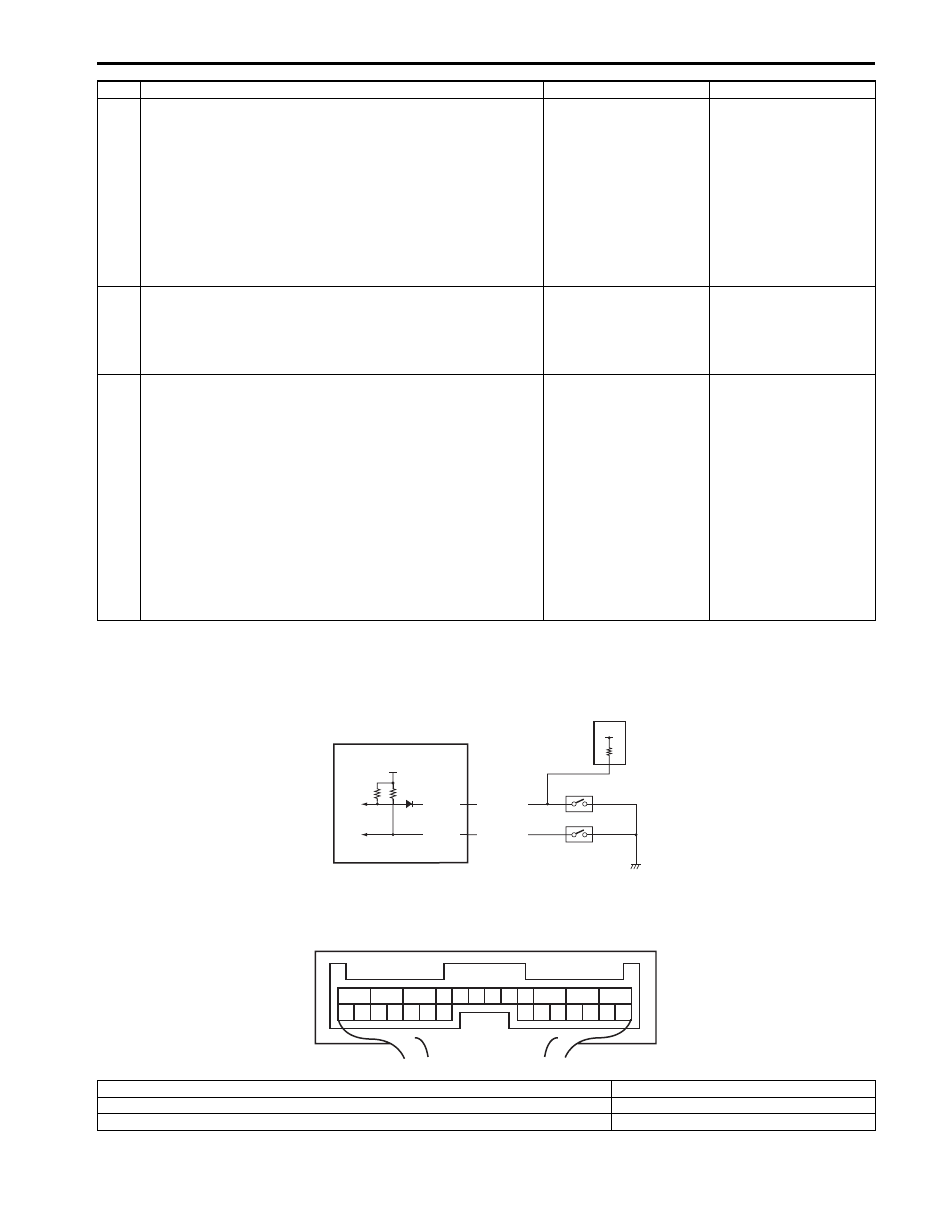
DTC C1237: Center Differential Lock Switch Circuit Open
S6JB0B3304021
Wiring Diagram
2
Transfer shift actuator circuit check
1) Disconnect transfer shift actuator connector “C54” with
ignition switch OFF.
2) Check for proper connection to “C54-1” and “C54-4”
terminals of transfer shift actuator connector.
3) If connection is OK, measure voltage between “C54-1”
or “C54-4” terminal of transfer shift actuator connector
and vehicle body ground.
Is it 10 – 14 V?
Go to Step 3.
Go to Step 4.
3
Transfer shift actuator check
1) Check transfer shift actuator referring to “Transfer
Is actuator in good condition?
Substitute a known-
good 4WD control
module and recheck.
Replace transfer shift
actuator.
4
Wire harness check
1) Disconnect connector from 4WD control module
connector “E91” with ignition switch OFF.
2) Check for open and high resistance or shorted to ground
in related circuits.
• Between “C54-1” terminal of transfer shift actuator
connector and “E91-22” terminal of 4WD control
module connector
• Between “C54-4” terminal of transfer shift actuator
connector and “E91-3” terminal of 4WD control
module connector
Are they in good condition?
Substitute a known-
good 4WD control
module and recheck.
Repair circuit.
Step
Action
Yes
No
IG
E91-13
E91-14
RED/GRN
PNK/WHT
2
3
4
12V
1
1
2
3
4
5
6
7
8
9
10
11
12
13
14
15
16
17
18
19
20
21
22
23
24
25
26
[A]
I5JB0A332018-01
[A]: 4WD control module connector “E91” (viewed from harness side)
3. 4L/N switch
1. 4WD control module
4. Center differential lock switch
2. TCM
Нет комментариевНе стесняйтесь поделиться с нами вашим ценным мнением.
Текст