Suzuki Grand Vitara JB627. Manual — part 159

3C-40 Transfer:
DTC Detecting Condition and Trouble Area
DTC Confirmation Procedure
1) Clear DTC using scan tool.
2) Select transfer switch to “4H” position and keep its position for 1 min.
3) Check DTC.
Troubleshooting
DTC detecting condition
Trouble area
Though transfer shift actuator motor position switch is “4H”
position, the ON signal is not input from the center differential
lock switch.
• Center differential lock switch
• Center differential lock switch circuit
• 4WD control module
Step
Action
Yes
No
1
Was “4WD control system check” performed?
Go to Step 2.
Go to “4WD Control
System Check”.
2
Center differential lock switch circuit check
1) Disconnect center differential lock switch connector with
ignition switch OFF.
2) Check for proper connection to terminal of center
differential lock switch connector.
3) If connection is OK, measure voltage between “RED/
GRN” terminal of center differential lock switch
connector and vehicle body ground with ignition switch
ON.
Is it 10 – 14 V?
Go to Step 3.
Go to Step 4.
3
Center differential lock switch check
1) Check center differential lock switch referring to
“Transfer Assembly Inspection”.
Is switch in good condition?
Substitute a known-
good 4WD control
module and recheck.
Replace center
differential lock switch.
4
Wire harness check
1) Disconnect connector from 4WD control module
connector “E91” with ignition switch OFF.
2) Check for proper connection to “E91-14” terminal of
4WD control module connector.
3) If OK, measure resistance between “RED/GRN” terminal
of center differential lock switch connector and “E91-14”
terminal of 4WD control module connector.
Is it 1
Ω
or less?
Substitute a known-
good 4WD control
module and recheck.
“RED/GRN” wire is
open or high resistance.
Transfer: 3C-41
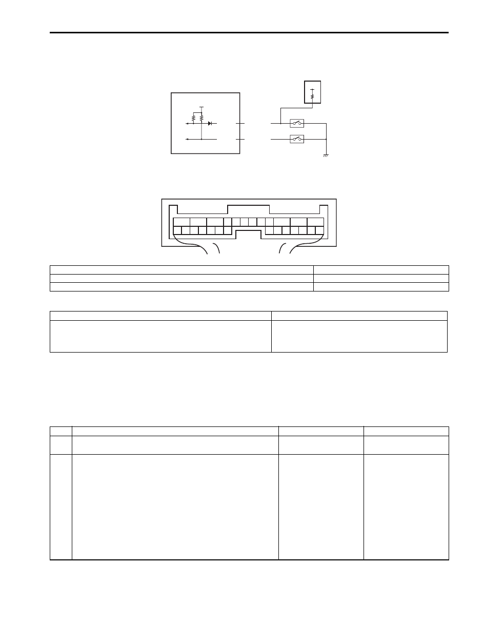
DTC C1238: Center Differential Lock Switch Circuit Short
S6JB0B3304022
Wiring Diagram
DTC Detecting Condition and Trouble Area
DTC Confirmation Procedure
1) Clear DTC using scan tool.
2) Select transfer switch to “4L-lock” position and keep its position for 1 min.
3) Check DTC.
Troubleshooting
IG
E91-13
E91-14
RED/GRN
PNK/WHT
2
3
4
12V
1
1
2
3
4
5
6
7
8
9
10
11
12
13
14
15
16
17
18
19
20
21
22
23
24
25
26
[A]
I5JB0A332018-01
[A]: 4WD control module connector “E91” (viewed from harness side)
3. 4L/N switch
1. 4WD control module
4. Center differential lock switch
2. TCM
DTC detecting condition
Trouble area
Though transfer shift actuator motor position switch is “4L-lock”
position, the OFF signal is not input from the center differential
lock switch.
• Center differential lock switch
• Center differential lock switch circuit
• 4WD control module
Step
Action
Yes
No
1
Was “4WD control system check” performed?
Go to Step 2.
Go to “4WD Control
System Check”.
2
Center differential lock switch circuit check
1) Disconnect center differential lock switch connector with
ignition switch OFF.
2) Check for proper connection to terminal of center
differential lock switch connector.
3) If connection is OK, measure voltage between “RED/
GRN” terminal of center differential lock switch
connector and vehicle body ground with ignition switch
ON.
Is it 10 – 14 V?
Go to Step 3.
Go to Step 4.
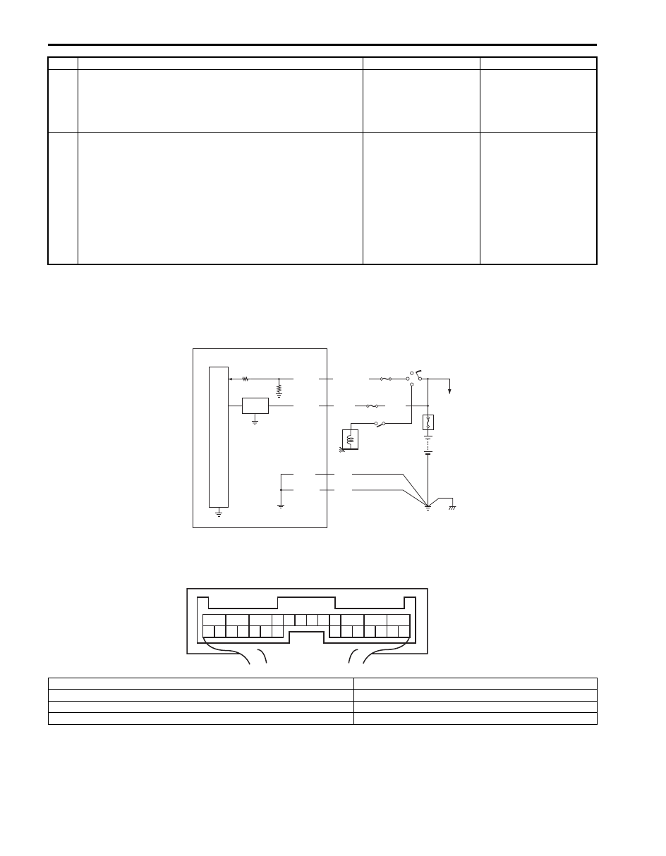
3C-42 Transfer:
DTC C1240: 4WD Control Module Power Supply Circuit Malfunction
S6JB0B3304023
Wiring Diagram
3
Center differential lock switch check
1) Check center differential lock switch referring to
“Transfer Assembly Inspection”.
Is switch in good condition?
Substitute a known-
good 4WD control
module and recheck.
Replace center
differential lock switch.
4
Wire harness check
1) Disconnect connector from 4WD control module
connector “E91” with ignition switch OFF.
2) Check for proper connection to “E91-14” terminal of
4WD control module connector.
3) If OK, measure resistance between “RED/GRN” terminal
of center differential lock switch connector and “E91-14”
terminal of 4WD control module connector.
Is it 1 M
Ω
or more?
Substitute a known-
good 4WD control
module and recheck.
“RED/GRN” wire is
shorted to ground
circuit.
Step
Action
Yes
No
5V
+BB
E91-12
E91-11
E91-10
E91-1
BLK
BLK
WHT
BLK/WHT
2
4
6
3
5
7
1
1
2
3
4
5
6
7
8
9
10
11
12
13
14
15
16
17
18
19
20
21
22
23
24
25
26
[A]
BLK
I5JB0A332019-01
[A]: 4WD control module connector “E91” (viewed from harness side)
4. “4WD” fuse
1. 4WD control module
5. Shift switch (for A/T model) or CPP switch (for M/T model)
2. “IG COIL” fuse
6. Main fuse box
3. Ignition switch
7. Starting motor

Transfer: 3C-43
DTC Detecting Condition and Trouble Area
DTC Confirmation Procedure
1) Clear DTC using scan tool.
2) Start engine and drive vehicle at 30 km/h (19 mph) or more vehicle speed at least for 1 min.
3) Stop vehicle and check DTC.
Troubleshooting
DTC C1243: Internal Circuit Malfunction of 4WD Control Module
S6JB0B3304024
DTC Detecting Condition and Trouble Area
DTC Confirmation Procedure
1) Clear DTC using scan tool.
2) Turn ignition switch to ON position for 60 seconds.
3) Check DTC.
Troubleshooting
Substitute a known-good 4WD control module and recheck.
DTC detecting condition
Trouble area
4WD control module power supply voltage is out of specification
while vehicle is running at 20 km/h (12 mph) or more.
• 4WD control module power supply circuit
Step
Action
Yes
No
1
Was “4WD control system check” performed?
Go to Step 2.
Go to “4WD Control
System Check”.
2
4WD control module power circuit check
1) Disconnect 4WD control module connector with ignition
switch OFF.
2) Check for proper connection to “E91” terminal of 4WD
control module connector.
3) If connection is OK, measure voltage between “E91-11”
terminal of 4WD control module connector and vehicle
body ground with ignition switch ON.
Is it 10 – 14 V?
Poor “E91-11”
connection or
intermittent trouble.
Check for intermittent
referring to “Intermittent
and Poor Connection
Inspection in Section
00”. If wire and
connections are OK,
substitute a known-
good 4WD control
module and recheck.
“4WD” fuse blown,
“WHT” or “BLK” wire is
circuit open or circuit
short.
DTC detecting condition
Trouble area
EEPROM Error
• 4WD control module
Нет комментариевНе стесняйтесь поделиться с нами вашим ценным мнением.
Текст