Suzuki Grand Vitara JB627. Manual — part 298
8B-18 Air Bag System:
Scan Tool Data
S6JB0B8204006
Data list of SDM
Scan Tool Data Definition
Back Up Volt (V): This parameter indicates the
capacity of the backup condenser installed to
maintain the ignition current (as much as possible)
even when the power supply to SDM that ignites the
inflator is shut off.
Battery Volt (V): Battery voltage is an analog input
signal read by SDM.
System ID (4ch/8ch): This parameter indicates the
number of initiator circuits.
Driv A/B Ini Res (Driver air bag initiator resistance)
(ohm): This parameter indicates the resistance of
the driver air bag initiator circuit.
Pass A/B Ini Res (Passenger air bag initiator
resistance) (ohm): This parameter indicates the
resistance of the passenger air bag initiator circuit.
Driv Pret Ini Res (Driver pretensioner initiator
resistance) (ohm): This parameter indicates the
resistance of the driver seat belt pretensioner
initiator circuit.
Pass Pret Ini Res (Passenger pretensioner initiator
resistance) (ohm): This parameter indicates the
resistance of the passenger seat belt pretensioner
initiator circuit.
LH Side Ini Res (Left side-air bag initiator resistance)
(ohm): This parameter indicates the resistance of
the left side-air bag initiator circuit.
RH Side Ini Res (Right side-air bag initiator
resistance) (ohm): This parameter indicates the
resistance of the right side-air bag initiator circuit.
LH Curtain Ini Res (Left side curtain-air bag initiator
resistance) (ohm): This parameter indicates the
resistance of the left side curtain-air bag initiator
circuit.
RH Curtain Ini Res (Right side curtain-air bag
initiator resistance) (ohm): This parameter
indicates the resistance of the right side curtain-air
bag initiator circuit.
“AIR BAG” Warning Light Comes ON Steady
S6JB0B8204007
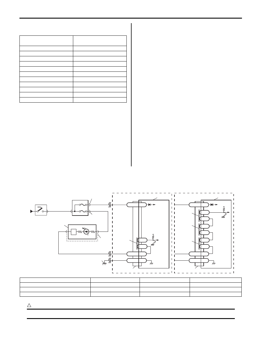
Wiring Diagram
CAUTION
!
Be sure to observe instructions under CAUTION in “Air Bag Diagnostic System Check Flow”.
Scan Tool Data
Normal Condition /
Reference Value
Battery volt
10 – 14 V
Back up volt
27.0 – 33.0 V
System ID
4ch or 8ch
Driv A/B Ini Res
2.1 – 3.8 ohm
Pass A/B Ini Res
1.8 – 2.8 ohm
Driv Pret Ini Res
1.8 – 2.9 ohm
Pass Pret Ini Res
1.8 – 2.9 ohm
LH Side Ini Res
1.8 – 2.6 ohm
RH Side Ini Res
1.8 – 2.6 ohm
LH Curtain Ini Res
1.8 – 2.8 ohm
RH Curtain Ini Res
1.8 – 2.8 ohm
BLK
G47-18
G47-20
L2
L1
GND
WL
“G47”
12V
1
2
6
8
4
5
RED
PPL/RED
BLK/YEL
YEL/BLK
BLK
RED
YEL/BLK
“G01”
7
“G28”
“G03”
G47-16
IG
[A]
G46-7
G46-16
L2
L1
GND
WL
“G46”
L4
L3
12V
G46-11
IG
[B]
L6
L5
3
10
10
9
9
9
9
11
I5JB0A820017-01
[A]: Without side-air bag and curtain-air bag
3. Junction block assembly
7. Light driver
11. Ground for air bag system
[B]: With side-air bag and curtain-air bag
4. “A/B” fuse
8. “AIR BAG” warning light
1. From main fuse
5. “METER” fuse
9. Connection detection pin
2. Ignition switch
6. Combination meter
10. SDM
Air Bag System: 8B-19
Flow Test Description
Step 1: Check for “AIR BAG” fuse blown.
Step 2: Check for loose connection between junction block assembly connector and junction block assembly.
Step 3: Check for loose connection between SDM connector and SDM.
Step 4: Check for SDM power supply circuit.
Step 5: Check for open or short circuit between “AIR BAG” warning light circuit and ground.
Troubleshooting
Step
Action
Yes
No
1
1) Turn ignition switch OFF.
2) Remove and inspect “A/B” fuse.
Is fuse good?
Go to Step 2.
“RED” wire short to
ground.
After repair, replace “A/
B” fuse.
2
1) Check for loose connection of junction block assembly
connector “G01”.
Is it connected securely?
Go to Step 3.
Correct connector “G01”
securely.
3
Check for loose connection of SDM connector “G47” or
“G46”.
Is it connected securely?
Go to Step 4.
Correct connector “G47”
or “G46” securely.
4
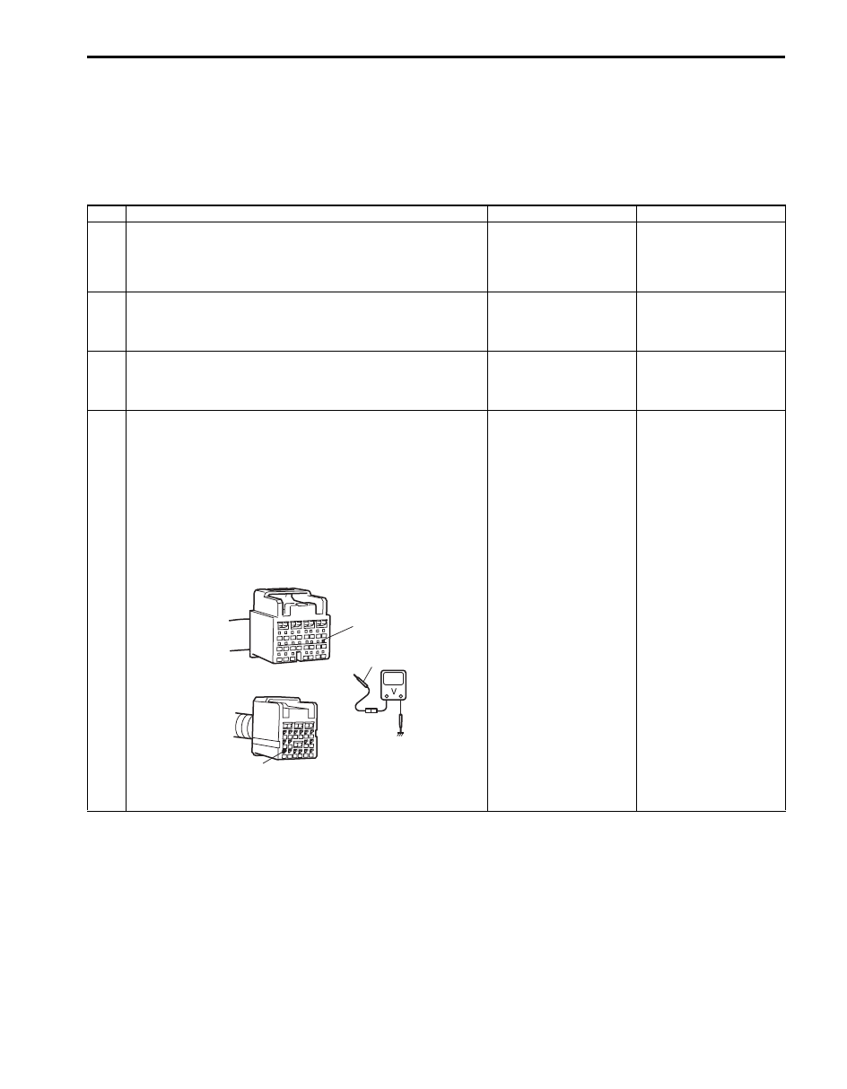
1) Disconnect SDM connector “G47” or “G46”.
2) Check proper connection to SDM at terminal “G47-16” or
“G46-11”.
3) If OK, then check voltage between “G47-16” terminal [A]
or “G46-11” terminal [B] of SDM connector and body
ground with ignition switch ON.
Special tool
(A): 09932–76010
Is it 8 V or more?
Go to Step 5.
“RED” wire (between “A/
B” fuse and SDM
connector) open or
“BLK/YEL” wire
(between ignition switch
and “A/B” fuse) open or
short to ground.
(A)
[A]
[B]
“G47-16”
“G46-11”
I5JB0A820018-01
8B-20 Air Bag System:
NOTE
Upon completion of inspection and repair work, perform the following items.
• Reconnect all air bag system components and ensure all components are properly mounted.
• Repeat “Air Bag Diagnostic System Check” to confirm that the trouble has been corrected.
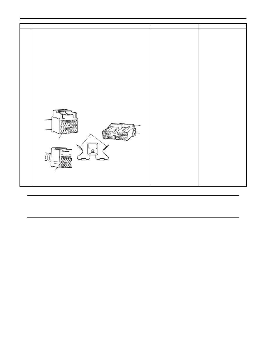
5
1) Disconnect combination meter connector “G28” referring
to “Combination Meter Removal and Installation in
Section 9C”.
2) Check proper connection to combination meter at “YEL/
BLK” terminal for “AIR BAG” warning light and to SDM at
terminal “G47-18” or “G46-7”.
3) If OK, then check resistance between “YEL/BLK” wire
terminal of combination meter connector “G28” and
“G47-18” terminal [A] or “G46-7” terminal [B] of SDM
connector.
Special tool
(A): 09932–76010
Is resistance 1
Ω
or less?
Substitute a known-
good SDM and recheck.
If “AIR BAG” warning
light remain lighting,
replace combination
meter.
“YEL/BLK” wire
(between combination
meter and SDM
connector) open or
short to ground.
Step
Action
Yes
No
(A)
[A]
[B]
“G47-18”
“G46-7”
I5JB0A820019-01
Air Bag System: 8B-21
“AIR BAG” Warning Light Does Not Come ON
S6JB0B8204008
Wiring Diagram
Refer to ““AIR BAG” Warning Light Comes ON Steady”.
CAUTION
!
Be sure to observe instructions under CAUTION in “Air Bag Diagnostic System Check Flow”.
Flow Test Description
Step 1: Check combination meter power feed circuit.
Step 2: Check “AIR BAG” warning light circuit.
Troubleshooting
NOTE
Upon completion of inspection and repair work, perform the following items.
• Reconnect all air bag system components and ensure all components are properly mounted.
• Repeat “Air Bag Diagnostic System Check” to confirm that the trouble has been corrected.
Step
Action
Yes
No
1
1) Set parking brake.
2) Note combination meter when ignition switch is turned
ON.
Does the “BRAKE” indicator (warning light) come ON?
Go to Step 2.
Check and correct the
following possible
cause.
• Open circuit in
“BLK/YEL” or “PPL/
RED” wire.
• Short
circuit between “BLK/
YEL” or “PPL/RED” and
ground.
• “METER” fuse
blown.
2
1) Disconnect SDM connector “G46” or “G47”.
2) Note combination meter when ignition switch is turned
ON.
Does the “AIR BAG” warning light come ON?
Substitute a known-
good SDM and recheck.
“YEL/BLK” circuit
shorted to power circuit.
If OK, replace
combination meter.
Нет комментариевНе стесняйтесь поделиться с нами вашим ценным мнением.
Текст