Suzuki Grand Vitara JB627. Manual — part 299
8B-22 Air Bag System:
“AIR BAG” Warning Light Flashes
S6JB0B8204009
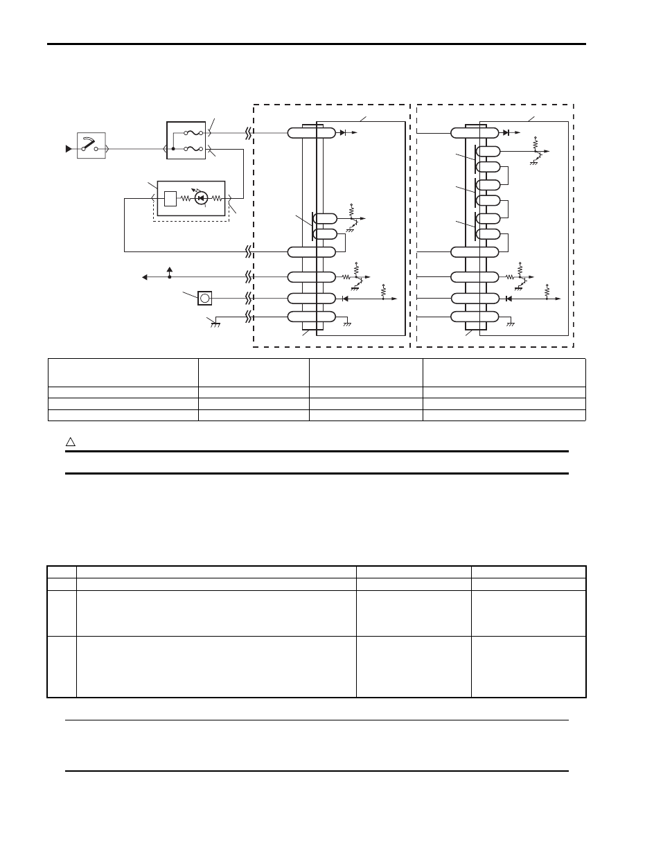
Wiring Diagram
CAUTION
!
Be sure to observe instructions under CAUTION in “Air Bag Diagnostic System Check Flow”.
Flow Test Description
Step 1: Check that vehicle is equipped with or without “AIR BAG” monitor connector.
Step 2: Check “AIR BAG” monitor coupler.
Step 3, 4: Check for short circuit between diagnosis switch circuit and ground.
Troubleshooting
NOTE
Upon completion of inspection and repair work, perform the following items.
• Reconnect all air bag system components and ensure all components are properly mounted.
• Repeat “Air Bag Diagnostic System Check” to confirm that the trouble has been corrected.
G47-14 DNS
BLK
G47-18
G47-20
L2
L1
GND
WL
“G47”
12V
1
2
6
8
4
5
RED
PPL/RED
BLK/YEL
YEL/BLK
“G01”
7
“G28”
“G03”
G47-16
IG
[A]
G46-7
G46-16
L2
L1
GND
WL
“G46”
L4
L3
12V
G46-11
IG
[B]
L6
L5
PPL/WHT
PPL
BLK
RED
YEL/BLK
PPL/WHT
PPL
“G34”
G46-9
ST
ST
G47-13
12V
12V
5V
G46-12 DNS
5V
11
12
3
14
9
13
13
9
9
9
10
I5JB0A820020-01
[A]: Without side-air bag and curtain-air
bag
3. Junction block assembly
7. Light driver
11. To ECM, TCM, BCM, ABS hydraulic unit /
control module assembly and 4WD
control module
[B]: With side-air bag and curtain-air bag
4. “A/B” fuse
8. “AIR BAG” warning light
12. “AIR BAG” monitor coupler (if equipped)
1. From main fuse
5. “METER” fuse
9. Connection detection pin
13. SDM
2. Ignition switch
6. Combination meter
10. To DLC
14. Ground for air bag system
Step
Action
Yes
No
1
Is vehicle equipped with “AIR BAG” monitor connector?
Go to Step 2.
Go to Step 3.
2
Check “AIR BAG” monitor coupler.
Is the diagnosis switch terminal in “AIR BAG” monitor
coupler connected to body ground with service wire?
Remove service wire.
Go to Step 3.
3
1) With ignition switch OFF, disconnect SDM connector
“G47” or “G46”.
2) Check “G47-14” or “G46-12” terminal of SDM connector.
Is it shorted to ground terminal or harness?
Clean up terminal or
harness.
Substitute a known-
good SDM and recheck.
Air Bag System: 8B-23
“AIR BAG” Warning Light Cannot Indicate Flashing Pattern of DTC (If Equipped with “AIR BAG”
Monitor Coupler)
S6JB0B8204010
Wiring Diagram
Refer to ““AIR BAG” Warning Light Flashes”.
CAUTION
!
Be sure to observe instructions under CAUTION in “Air Bag Diagnostic System Check Flow”.
Flow Test Description
Step 1: Check “AIR BAG” monitor coupler.
Step 2: Check for open circuit in air bag diagnosis switch circuit.
Troubleshooting
NOTE
Upon completion of inspection and repair work, perform the following items.
• Reconnect all air bag system components and ensure all components are properly mounted.
• Repeat “Air Bag Diagnostic System Check” to confirm that the trouble has been corrected.
Step
Action
Yes
No
1
Inspect connection between diagnostic switch terminal on
“AIR BAG” monitor coupler and body ground with service
wire.
Are they connected securely with service wire?
Go to Step 2.
Properly connect
diagnostic switch
terminal on “AIR BAG”
monitor coupler and
body ground with
service wire.
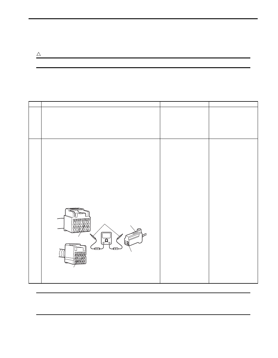
2
1) Disconnect SDM connector from SDM.
2) Check for proper connection at “PPL” wire (“G47-14”
terminal or “G46-12” terminal of SDM connector and
“G34-2” terminal of “AIR BAG” monitor coupler (1))
terminals.
3) If OK, then measure resistance between “G47-14”
terminal [A] or “G46-12” terminal [B] and “G34-2”
terminal.
Special tool
(A): 09932–76010
Is resistance 1
Ω
or more?
Check “PPL” wire
terminals. If OK, repair
high resistance or open
in “PPL” wire circuit.
Substitute a known
good SDM and recheck.
[A]
[B]
(A)
1
“G47-14”
“G46-12”
“G34-2”
I5JB0A820021-02

8B-24 Air Bag System:
DTC B1013: SDM fault
S6JB0B8204011
DTC Will Set when
An internal SDM fault is detected by SDM.
NOTE
DTC B1013 can never be cleared once it has been set.
DTC Troubleshooting
1) Turn ignition switch OFF.
2) Replace SDM.
3) Repeat “Air Bag Diagnostic System Check”.
DTC B1016: Power Source Voltage High
S6JB0B8204012
Wiring Diagram
CAUTION
!
Be sure to observe instructions under CAUTION in “Air Bag Diagnostic System Check Flow”.
DTC Will Set when
The power source voltage to SDM is above specified value for specified time.
Flow Test Description
Step 1: Check if voltage applied to SDM is within normal range.
Step 2: Check if DTC B1016 still exists.
BLK
G47-20 GND
“G47”
1
2
4
3
RED
BLK
RED
BLK/YEL
“G01”
G47-16
IG
[A]
G46-16 GND
“G46”
G46-11
IG
[B]
6
5
5
I5JB0A820022-01
[A]: Without side-air bag and curtain air bag
1. From main fuse
3. “A/B” fuse
5. SDM
[B]: With side-air bag and curtain air bag
2. Ignition switch
4. Junction block assembly
6. Ground for air bag system
Air Bag System: 8B-25
DTC Troubleshooting
NOTE
Upon completion of inspection and repair work, perform the following items.
• Reconnect all air bag system components and ensure all components are properly mounted.
• Clear DTCs referring to “DTC Clearance”, if any.
• Repeat “Air Bag Diagnostic System Check” to confirm that the trouble has been corrected.
Step
Action
Yes
No
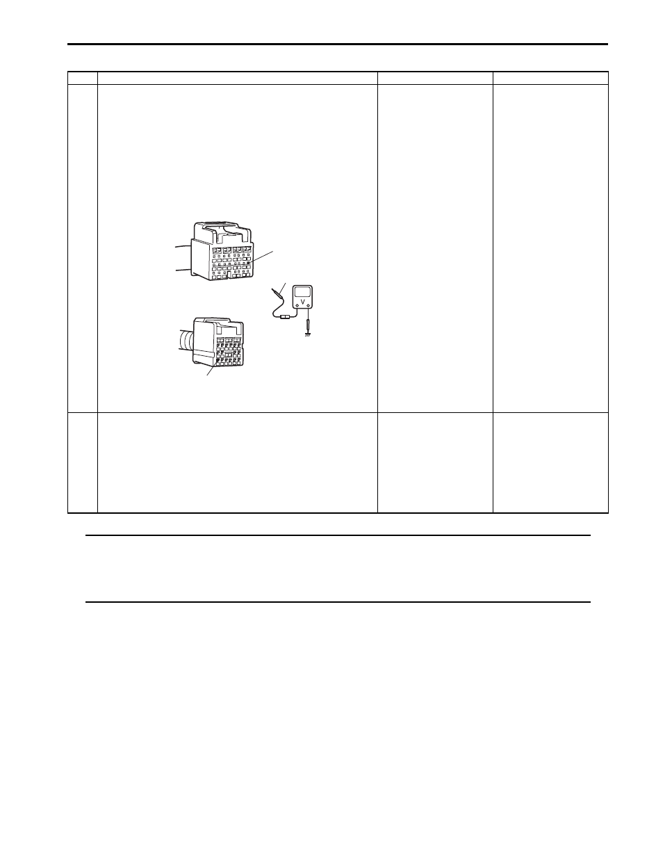
1
1) With ignition switch OFF, disconnect SDM connector.
2) Check proper connection to SDM at “G47-16” or “G46-
11” terminal.
3) If OK, turn ignition switch ON and then check voltage
between “G47-16” [A] or “G46-11” [B] terminal on SDM
connector and body ground.
Special tool
(A): 09932–76010
Is voltage 14 V or less?
Go to Step 2.
Check charging system
and repair as necessary
referring to “Generator
Test (Overcharged
Battery Check) in
Section 1J”.
2
1) With ignition switch OFF, reconnect SDM connector.
With ignition switch ON, is DTC B1016 indicated?
Substitute a known-
good SDM and recheck.
Intermittent trouble.
Check for intermittent
trouble referring to
“Inspection of
Intermittent and Poor
Connections” If OK,
substitute a known-
good SDM and recheck.
(A)
[A]
[B]
“G46-11”
“G47-16”
I5JB0A820023-01
Нет комментариевНе стесняйтесь поделиться с нами вашим ценным мнением.
Текст