Suzuki Grand Vitara JB627. Manual — part 250
5B-23 Manual Transmission/Transaxle:
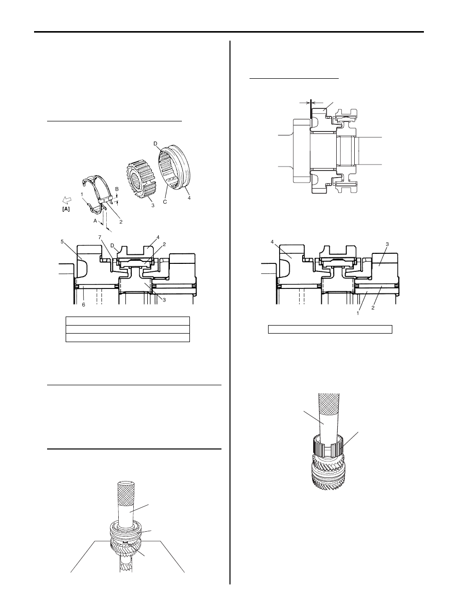
5) Assemble synchronizer sleeve (4) and hub (3) as
follows.
a) Fit high speed synchronizer sleeve to hub in
specified direction as shown in figure.
b) Insert 3 keys (2) to hub.
c) Set springs (1) at specified position as shown in
figure.
Synchronizer key installation position
: A = B
6) Drive in high speed synchronizer assembly (1) using
special tool and hammer.
NOTE
• While press-fitting sleeve & hub, make
sure that synchronizer ring key slots (2)
are aligned with keys in sleeve & hub
assembly.
• Check free rotation of 4th gear after press
fitting sleeve & hub assembly.
Special tool
(A): 09913–84510
7) Check 4th gear (1) thrust clearance by using
thickness gauge. If clearance is out of specification,
repress-fit or replace defective part.
4th gear thrust clearance
“a”: 0.10 – 0.25 mm (0.004 – 0.010 in.)
8) Apply oil to high speed gear needle bearing, and
then install 3rd gear bush (1), high speed gear
needle bearing (2) and 3rd gear (3).
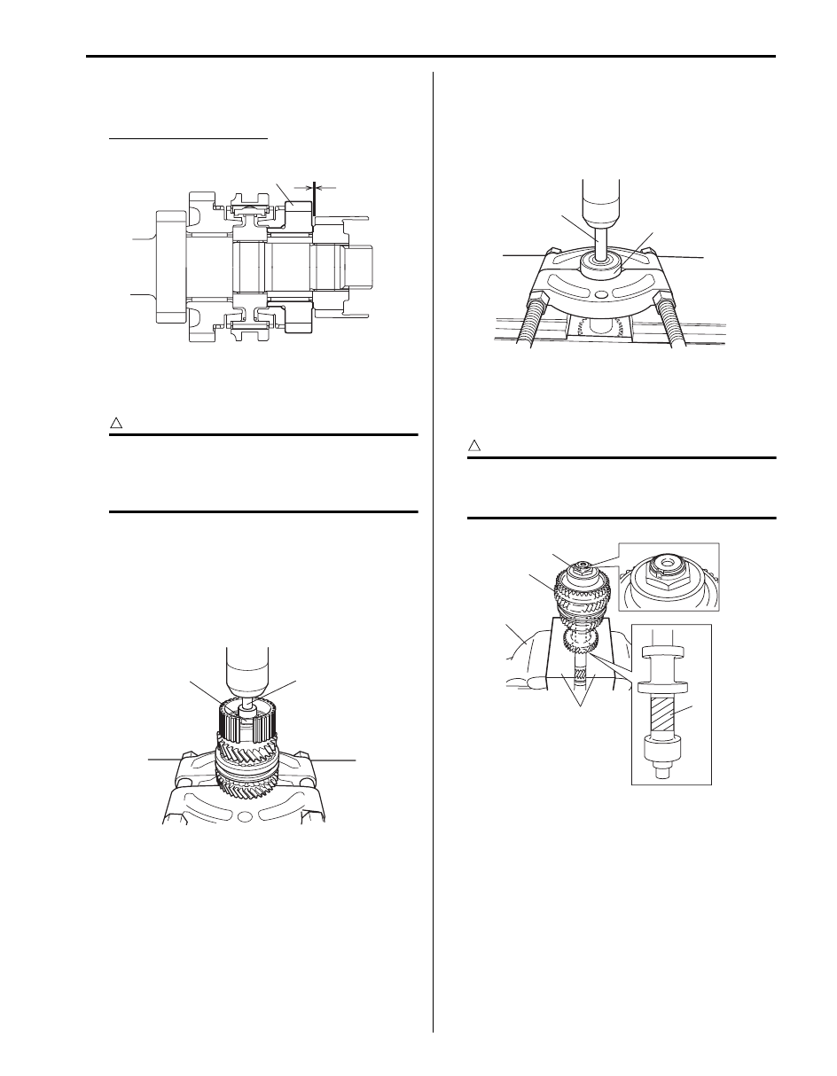
9) Press-fit 5th speed synchronizer hub (1) using
special tool and hammer.
Special tool
(A): 09913–84510
[A]: 4th gear side
C: Key way
D: Projecting end
I5JB0A520060-01
(A)
1
2
I5JB0A520061-01
4. 4th gear
“a”
1
I5JB0A520062-01
I5JB0A520063-01
(A)
1
I5JB0A520064-01
Manual Transmission/Transaxle: 5B-24
10) Check 3rd gear (1) thrust clearance by using
thickness gauge. If clearance is out of specification,
repress-fit or replace defective part.
3rd gear thrust clearance
“a”: 0.10 – 0.25 mm (0.004 – 0.010 in.)
11) Tighten input shaft 5th hub nut to specified torque in
the same manner as step 4) of “Input Shaft
Disassembly”.
CAUTION
!
Do not hold spline, gear teeth or abrasived
surface of shaft with vise through “V” blocks
or the like, otherwise shaft components may
be damaged.
Tightening torque
Input shaft 5th hub nut: 210 N·m (21.0 kgf-m,
152.0 lb-ft)
12) Caulk input shaft 5th hub nut (2) using caulking tool.
13) Drive in new input shaft union (1) using puller and
hydraulic press.
Countershaft Disassembly and Assembly
S6JB0B5206025
Disassembly
1) Remove countershaft rear bearing (1) using bearing
puller, metal stick (2) and hydraulic press.
2) Hold hatched area (5) of countershaft assembly (1)
with “V” blocks (4) on vise (2) or the like to stop
rotation of shaft, undo caulking and countershaft
front bearing nut (3).
CAUTION
!
Do not hold spline, gear teeth or abrasived
surface of shaft with “V” blocks on vise or
the like, otherwise shaft may be damaged.
“a”
1
I5JB0A520065-01
1
2
I5JB0A520066-01
1
2
I5JB0A520067-01
5
1
2
3
4
I5JB0A520068-01
5B-25 Manual Transmission/Transaxle:
3) Apply bearing puller to 2nd gear (1), and drive out
countershaft front bearing (2), countershaft reverse
gear (3), 1st gear (4), countershaft gear needle
bearings, countershaft low needle bearing bush, low
speed synchronizer assembly (5) and 2nd gear all at
once from countershaft using metal stick (6) and
hydraulic press.
CAUTION
!
To avoid gear teeth from being damaged,
support 2nd gear at flat side of bearing puller.
Assembly
1) Clean all components thoroughly, inspect them for
any abnormality and replace with new ones as
necessary.
2) To ensure lubrication, air blow oil holes (1) and make
sure that they are free from any obstruction.
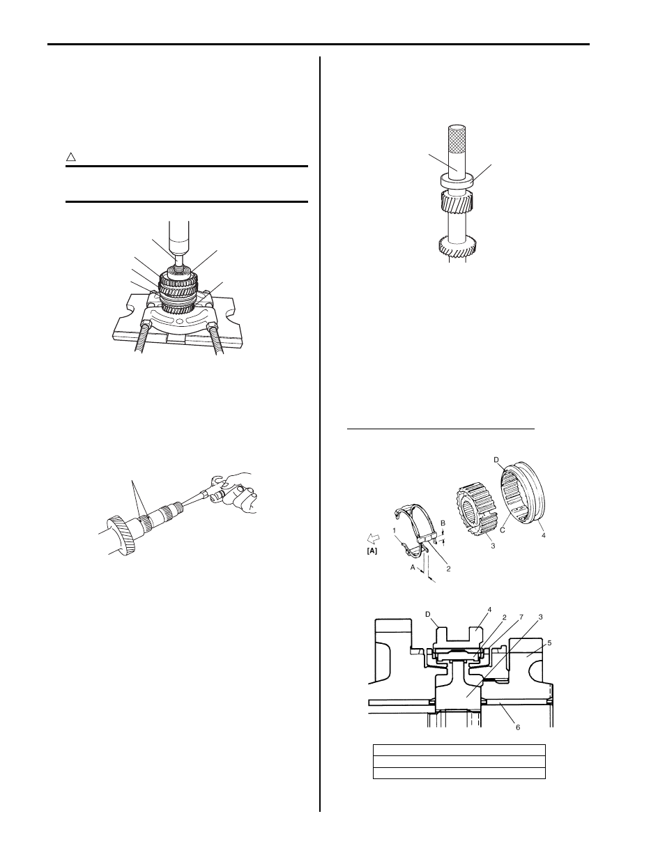
3) Drive in countershaft rear bearing (1) using special
tool and hammer.
Special tool
(A): 09913–84510
4) Apply oil to countershaft gear needle bearing (6),
and then install needle bearing, 2nd gear (5) and low
speed synchronizer ring (7).
5) Assemble synchronizer sleeve (4) and hub (3) as
follows.
a) Fit low speed synchronizer sleeve to hub in
specified direction as shown in figure.
b) Insert 3 keys (2) to hub.
c) Set springs (1) at specified position as shown in
figure.
Synchronizer key installation position
: A = B
2
1
6
3
4
5
I5JB0A520069-01
1
I5JB0A520070-01
[A]: 1st gear side
C: Key way
D: Chamfered side
1
(A)
I5JB0A520071-01
I5JB0A520072-01

Manual Transmission/Transaxle: 5B-26
6) Drive in low speed synchronizer assembly (1) using
special tool and hammer.
NOTE
• While press-fitting sleeve & hub, make
sure that synchronizer ring key slots (2)
are aligned with keys in sleeve & hub
assembly.
• Check free rotation of 2nd gear after press-
fitting sleeve & hub assembly.
Special tool
(A): 09913–84510
7) Check 2nd gear (1) thrust clearance by using
thickness gauge. If clearance is out of specification,
repress-fit or replace defective part.
2nd gear thrust clearance
“a”: 0.10 – 0.25 mm (0.004 – 0.010 in.)
8) Apply oil to countershaft gear needle bearing, and
then countershaft low needle bush, needle bearing
and 1st gear (1) to countershaft.
9) Press-fit countershaft reverse gear (2) using special
tool and hammer.
Special tool
(A): 09913–80113
10) Press-fit countershaft front bearing (1) using special
tool and hammer.
Special tool
(A): 09913–84510
11) Check low gear (1) thrust clearance by using
thickness gauge. If clearance is out of specification,
repress-fit or replace defective part.
Low gear thrust clearance
“a”: 0.10 – 0.25 mm (0.004 – 0.010 in.)
1
2
(A)
I5JB0A520073-01
1
“a”
I5JB0A520074-01
1
(A)
2
I5JB0A520075-01
1
(A)
I5JB0A520076-01
“a”
1
I5JB0A520077-01
Нет комментариевНе стесняйтесь поделиться с нами вашим ценным мнением.
Текст