Suzuki Grand Vitara JB627. Manual — part 248
5B-15 Manual Transmission/Transaxle:
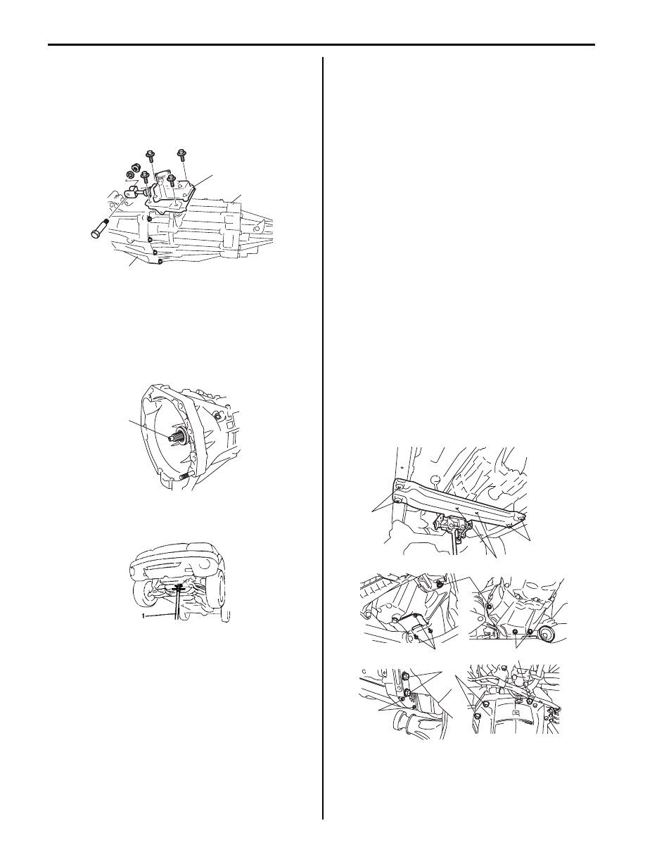
15) After removing mounting member, move rearward
transmission and transfer assemblies placed on jack
and then lower them.
16) Separate gear shift control lever rear case assembly
(2) and transfer assembly (3) from transmission
assembly (1).
Remounting
For remounting, reverse dismounting procedure.
• Apply grease to input shaft.
“A”: Grease 99000–25010 (SUZUKI Super Grease
A)
• Slant the rear of the engine down, using support
device (1) and install transmission to engine.
• Use specified torques as given below.
Tightening torque
Transmission to engine bolt and nut (a): 85 N·m (
8.5 kgf-m, 61.5 lb-ft)
Engine rear mounting member bolt (b): 55 N·m (
5.5 kgf-m, 40.0 lb-ft)
Clutch housing lower plate bolt (c): 11 N·m (1.1
kgf-m, 8.0 lb-ft)
Engine rear mounting No.2 bolt (d): 55 N·m (5.5
kgf-m, 40.0 lb-ft)
• Set each clamp for wiring and hose securely.
• Install shift control lever referring to “Transmission
Shift Control Lever Removal and Installation”.
• Connect clutch fluid joint to pipe of clutch operating
cylinder assembly referring to “Clutch Operating
Cylinder Assembly Removal and Installation in
Section 5C”.
• Install exhaust No.2 pipe referring to “Exhaust System
• Fill gear oil to transmission referring to “Manual
• Fill gear oil to transfer referring to “Transfer Oil
• Connect battery and check function of engine, clutch,
transmission and transfer.
• Install propeller shafts referring to “Propeller Shaft
Removal and Installation in Section 3D”.
2
1
3
I5JB0A520030-03
“A”
I5JB0A520031-01
I3JA01520024-01
(a)
(a)
(a)
(c)
(c)
(b)
(b)
(d)
I5JB0A520032-01
Manual Transmission/Transaxle: 5B-16
Manual Transmission Unit Disassembly
S6JB0B5206019
1) Remove clutch operating cylinder assembly from
transmission front case referring to “Clutch
Operating Cylinder Assembly Removal and
Installation in Section 5C”
2) Remove gear shift control lever rear cause assembly
and gear shift lever front case assembly referring to
“Gear Shift Control Lever Rear Case Assembly
Removal and Installation” and “Gear Shift Lever
Front Case Assembly Removal and Installation”.
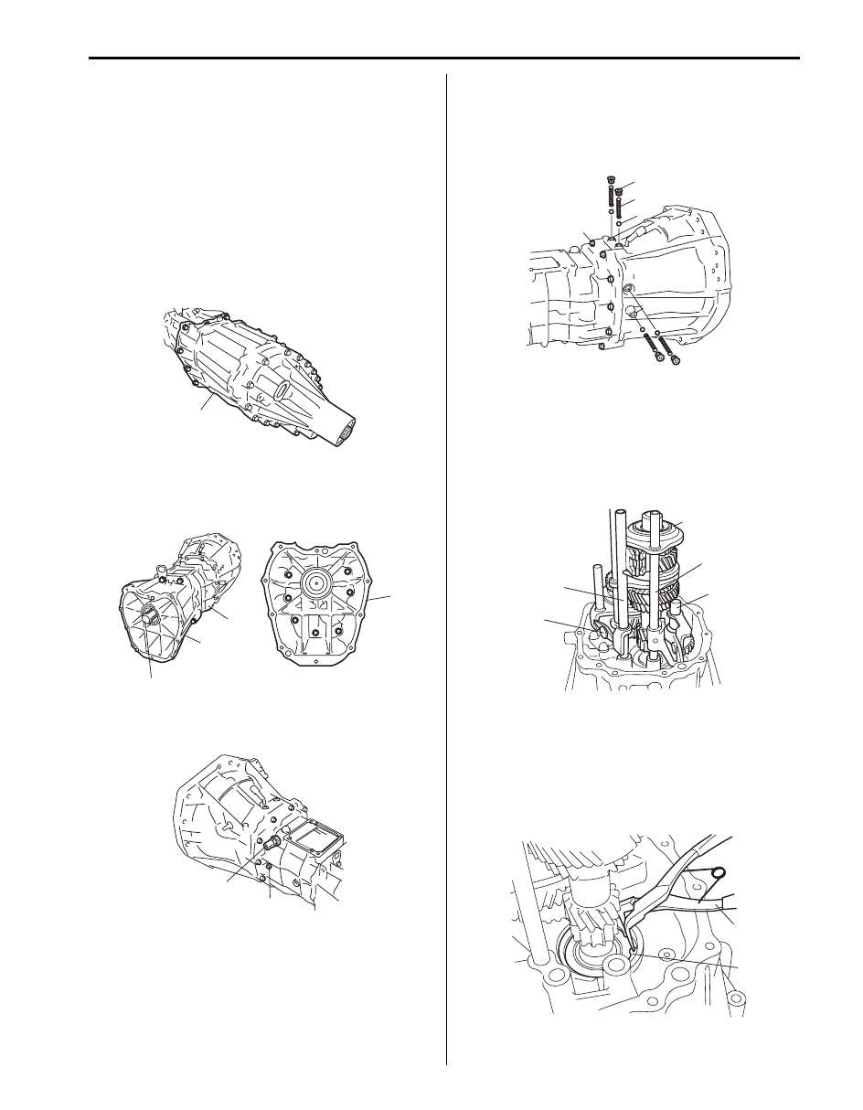
3) Separate transfer assembly (1) from transmission
assembly.
4) Remove adapter case (1) from rear case (2).
5) Remove output shaft assembly (3) from adapter
case.
6) Remove reverse shaft bolt (1) and back up light
switch (2).
7) Remove gear shift locating bolts (1), then take out
locating springs (2) and gear shift shaft balls (3).
8) Remove rear to front case bolts (4), then separate
rear case from front case tapping front case flange
with plastic hammer.
9) Remove oil gutter.
10) Remove reverse shaft assembly (1).
11) Remove low gear shift inverse lever (4).
12) Remove low speed gear shift shaft (2) and 5th &
reverse gear shift fork (3) with 5th speed
synchronizer sleeve (5).
13) Remove input shaft needle bearing, 5th speed
synchronizer ring and 5th speed synchronizer levers.
14) Remove input shaft front bearing circlip (1) from
case using special tool.
Special tool
(A): 09900–06106
1
I5JB0A520033-01
1
2
3
1
I5JB0A520034-01
2
1
I5JB0A520035-01
1
2
3
4
I5JB0A520036-01
3
5
1
2
4
I5JB0A520037-01
(A)
1
I5JB0A520038-01
5B-17 Manual Transmission/Transaxle:
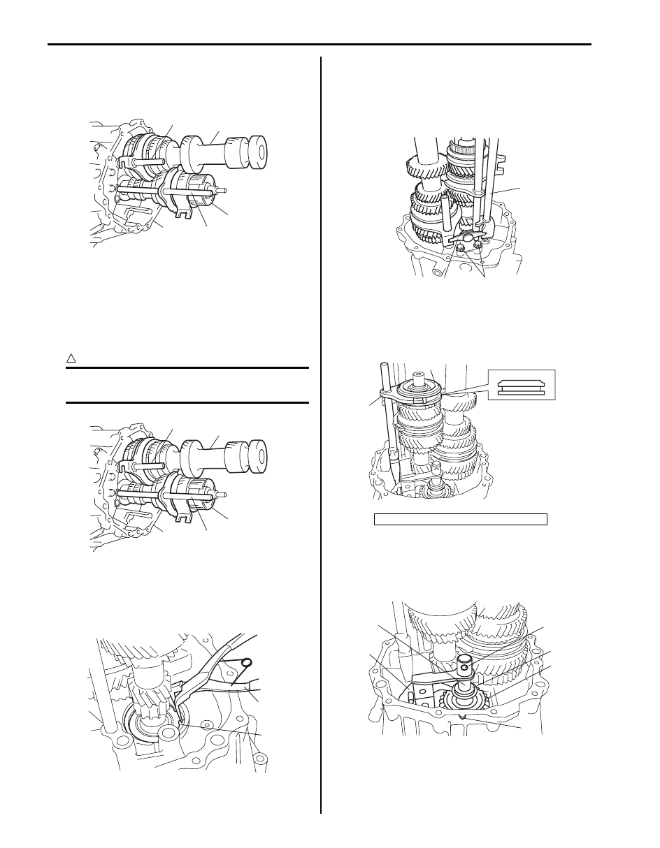
15) Remove input shaft assembly (1), countershaft
assembly (2), high speed gear shift fork (3) and low
speed gear shift fork (4) as assembly from front case
(5) tapping input shaft end by plastic hammer lightly.
Manual Transmission Unit Reassembly
S6JB0B5206020
1) Assemble input shaft assembly (1), countershaft
assembly (2), high speed gear shift fork (3) and low
speed gear shift fork (4), then install them all
together into front case (5).
CAUTION
!
Take care not to damage oil seal lip by input
shaft, or oil leakage may take place.
2) Install input shaft front bearing snap ring (1) using
special tool.
Special tool
(A): 09900–06106
3) Install low speed gear shift shaft (1) and low gear
shift inverse lever (2) and tighten with new bolt (3).
Tightening torque
Low gear shift inverse lever bolt (a): 23 N·m (2.3
kgf-m, 17.0 lb-ft)
4) Fit 5th & reverse gear shift fork (1) to 5th speed
synchronizer sleeve (2), and install them into input
shaft and front case in specified direction as shown
in figure.
5) Set reverse idler gear (1), reverse gear shift lever (2)
and reverse gear shaft washer (4), insert reverse
gear shaft (3) into case through idler gear and then
align hole “B” in shaft with protrusion “A” in case.
1
2
3
5
4
I5JB0A520039-01
1
2
3
5
4
I5JB0A520039-01
(A)
1
I5JB0A520040-01
A: Chamfered side
1
2
3, (a)
I5JB0A520041-02
1
2
A
I5JB0A520042-01
“B”
1
4
2
3
“A”
I5JB0A520043-01
Manual Transmission/Transaxle: 5B-18
6) Install oil gutter.
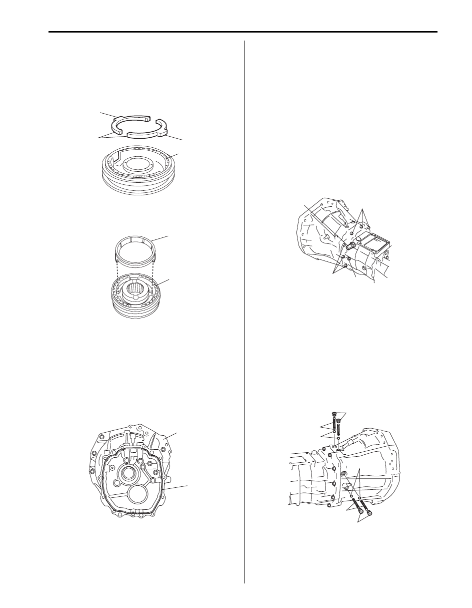
7) Install 5th speed synchronizer levers and 5th speed
synchronizer ring as follows.
a) Fit 5th speed synchronizer levers (1) to hub (2)
aligning protrusion “A” of 5th speed synchronizer
levers with groove of hub.
b) Install synchronizer ring (1) to hub (2) in
specified direction as shown in figure.
8) Install input shaft needle bearing to end of input
shaft.
9) Clean mating surfaces of both front and rear cases,
and uniformly apply sealant to front case (1) as
shown in figure by such amount that its section is 1.2
mm (0.047 in.) in diameter, and then mate it with rear
case.
“A”: Sealant 99000–31260 (SUZUKI Bond
No.1217G)
10) Install rear case to front case. Tighten case bolts (1)
to specified torque.
Tightening torque
Transmission case bolt (a): 23 N·m (2.3 kgf-m,
17.0 lb-ft)
11) Apply thread lock cement to reverse shaft bolt (2),
and tighten it.
“B”: Thread lock cement 99000–32110 (Thread
Lock Cement Super 1322)
Tightening torque
Reverse shaft bolt (b): 23 N·m (2.3 kgf-m, 17.0
lb-ft)
12) Install back up light switch (3) referring to “Back Up
Light Switch Removal and Installation”.
13) Apply grease to gear shift shaft balls (1) and locating
springs (2), then install them.
Apply thread lock cement to gear shift locating bolts
(3), and then tighten them.
“A”: Grease 99000–25010 (SUZUKI Super
Grease A)
“B”: Thread lock cement 99000–32110 (Thread
Lock Cement Super 1322)
Tightening torque
Gear shift locating bolt (a): 23 N·m (2.3 kgf-m,
17.0 lb-ft)
1
2
“A”
“A”
I5JB0A520044-01
1
2
I5JB0A520045-01
1
“A”
“A”
I5JB0A520046-01
1, (b)
3
1, (b)
2, “B”, (a)
I5JB0A520047-01
3, “B”, (a)
3, “B”, (a)
2, “A”
2, “A”
1, “A”
1, “A”
I5JB0A520048-01
Нет комментариевНе стесняйтесь поделиться с нами вашим ценным мнением.
Текст