Suzuki Grand Vitara JB627. Manual — part 207
5A-12 Automatic Transmission/Transaxle:
Schematic and Routing Diagram
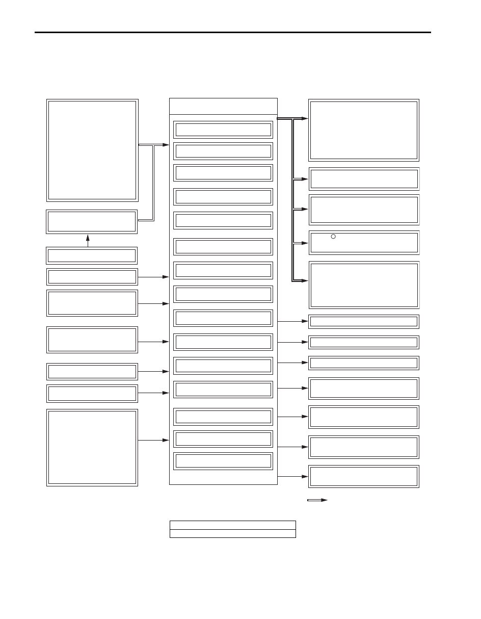
Electronic Shift Control Input / Output Diagram
S6JB0B5102003
INPUT
OUTPUT
TCM
ECM
-Accelerator pedal
position
-Coolant temperature
-Throttle position
-Engine torque
-Engine speed
-A/C ON/OFF
-Stop lamp switch
-Vehicle speed
-Cruise control signal
Gear shift control
Shift timing control
5th gear inhibit control
Slope shift control
Cruise shift control
Lock up control
Slip control
Torque control
Line pressure control
Overrun control
Reverse control
Squat control
Input shaft speed
sensor
Output shaft speed
sensor
"4" position switch
ATF temp. sensor
Transfer 4L/N switch
Transmission range
sensor
- Range "P" signal
- Range "R" signal
- Range "N" signal
- Range "D" signal
- Range "3" signal
- Range "L" signal
Fail safe function
Self diagnosis
Warning function
ECM
-Transmission output speed
-Shift position signal
-Shift position signal
-Shift position signal
-Transmission fluid temperature
-Transmission actual gear
-Transmission actual gear
-Transmission emissions
reated malfunction
Combination meter
-Shift indicator
-POWER mode lamp
-MIL *1
-Transmission warning light *2
BCM
ESP control module
Shift solenoid valve-A
Shift solenoid valve-B
Shift solenoid valve-E
TCC pressure control
solenoid valve
Pressure control
solenoid valve-A
Pressure control
solenoid valve-B
Pressure control
solenoid valve-C
Signal on CAN
communincation line
BCM
-P/N mode signal
P/N mode switch
R
-Transmission actual gear
4WD control module
I6JB0B510003-02
*1: E-OBD model
*2: Non-E-OBD model
Automatic Transmission/Transaxle: 5A-13
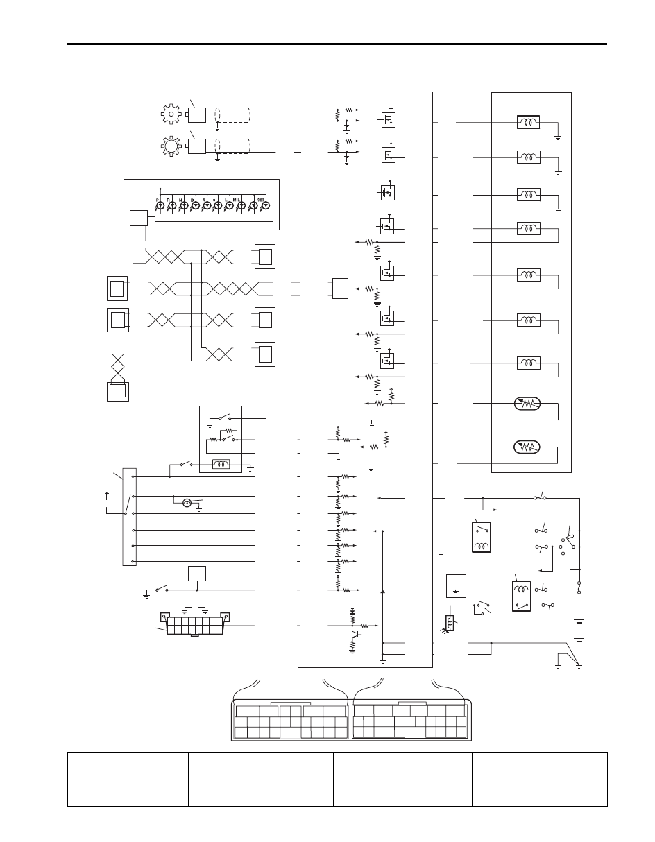
Electronic Shift Control System Wiring Diagram
S6JB0B5102004
21
22
23
5V
17
18
19
24
20
12V
12V
12V
12V
12V
12V
12V
6
5
16 15 14 13 12 11
4 3
24 23
21
22
10 9
8
7
2
1
19
20
18 17
E92
17 16
26 25
15 14
6
5
3
4
2
13 12
23 22
24
11 10 9
21 20 19
8 7
18
1
E93
[A]
BLK
BLK/ORN
BLK/ORN
BLK/WHT
+BB
WHT
32
26
31
27
28
29
30
34
35
RED
BLU
WHT
P
N
5
IG11
33
BLK/WHT
13
37
37
37
3
4
38
6
7
8
5
37
11
10
12
36
P
R
N
D
3
2
14
IG11
BLK/RED
WHT
WHT/BLU
RED
WHT
RED
WHT/RED
RED
YEL/GRN
PNK/BLU
PNK/GRN
PNK/WHT
YEL/BLK
YEL/RED
GRN/ORN
GRN/WHT
E93-9
E93-21
E93-4
E93-20
E93-1
E93-8
E93-7
E93-19
E93-18
E92-17
E92-7
12V
37
WHT
RED
37
WHT
RED
37
WHT
RED
RED
2.5V
WHT
ORN
1
2
E93-5
E93-14
2.5V
BLU
PNK
E93-6
E93-16
15
6
12V
16
E93-23
PPL/WHT
E92-14
E92-3
E92-11
E92-12
E92-16
E92-15
E92-5
E92-2
E92-4
E92-9
E92-22
E92-19
E92-21
E92-1
E92-23
E92-6
E92-24
9
37
WHT
WHT
RED
5V
25
E92-20
E92-10
GRN
GRN/RED
GRN/BLK
GRN/YEL
PPL/WHT
YEL/RED
BRN/RED
LT GRN/BLK
LT GRN
BRN/BLU
YEL/BLK
ORN
GRY/BLU
GRY
TML
LT GRN/RED
I6JB0B510004-02
1. Output shaft speed sensor
11. Shift lock solenoid
21. Pressure control solenoid valve-A
31. Ignition switch
2. Input shaft speed sensor
12. Brake light switch
22. Pressure control solenoid valve-B
32. AT relay in integration relay No.2
3. Combination meter
13. Transmission range sensor
23. Pressure control solenoid valve-C
33. Starting motor relay
4. ABS/ESP
® control module
14. Back-up light
24. Transmission fluid temperature
sensor A
34. Inhibit switch

5A-14 Automatic Transmission/Transaxle:
5. ECM
15. Transfer 4L/N switch
25. Transmission fluid temperature
sensor B (if equipped)
35. Starting motor
6. 4WD control module (if
equipped)
16. DLC
26. “DOME” fuse
36. Meter driver
7. Keyless start control module
(keyless start model)
17. Shift solenoid valve-A
27. “AT” fuse
37. CAN driver
8. BCM
18. Shift solenoid-B
28. “IG COIL” fuse
38. Steering angle sensor (ESP
®
model)
9. P/N mode switch
19. Shift solenoid valve-E
29. “ST SIG” fuse
[A]: TCM connector (viewed from
harness side)
10. “4” position switch
20. TCC pressure control solenoid valve
30. “ST” fuse
Automatic Transmission/Transaxle: 5A-15
Component Location
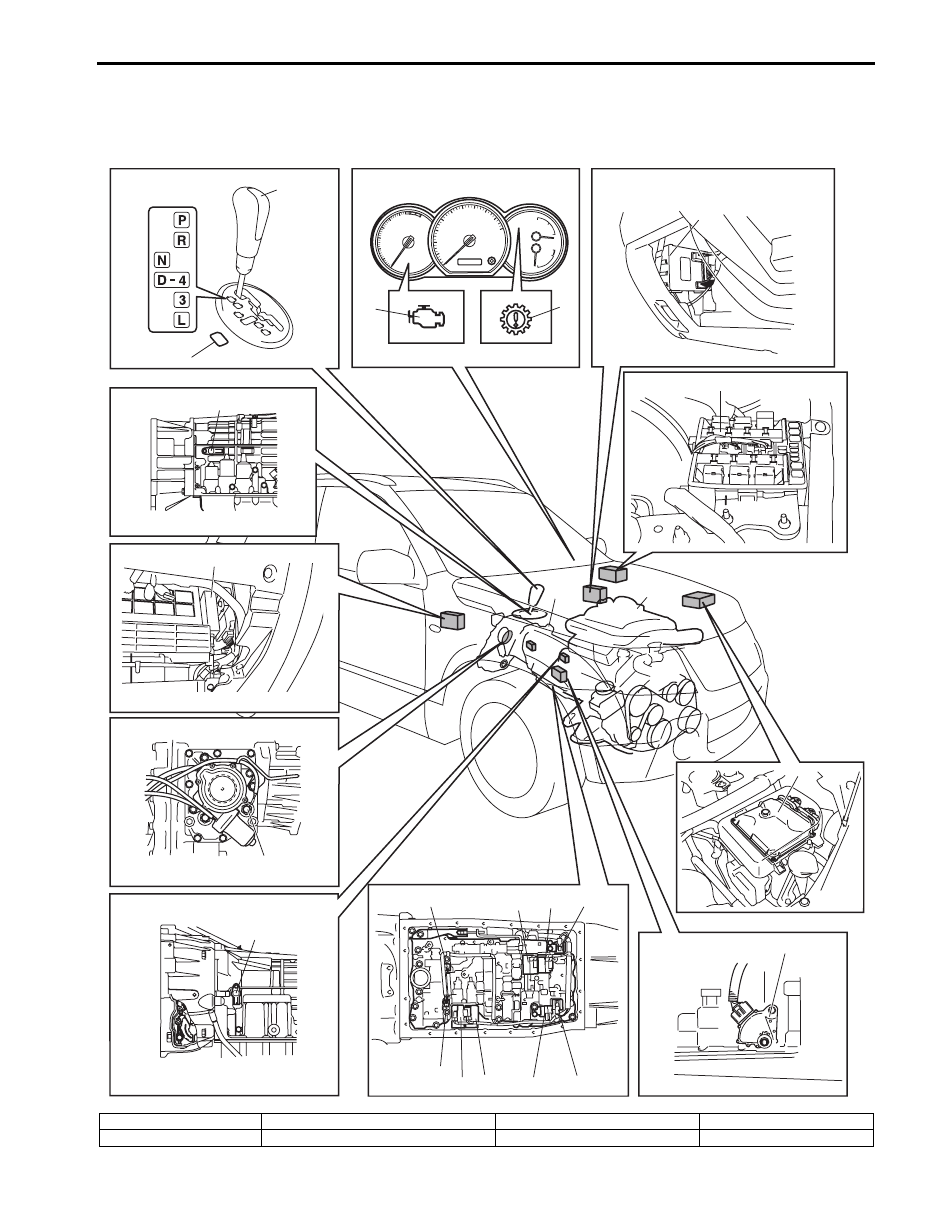
Electronic Shift Control System Components Location
S6JB0B5103001
4
21
1
2
20
19
18
17
16
10
12
11
13
14
15
9
8
7
6
5
22
3
23
I6JB0B510005-02
1. Engine
7. TCM
13. Pressure control solenoid valve-B
19. Transmission range sensor
2. Transmission
8. Transfer 4L/N switch
14. Shift solenoid valve-A
20. ECM
Нет комментариевНе стесняйтесь поделиться с нами вашим ценным мнением.
Текст