Suzuki Grand Vitara JB627. Manual — part 214
5A-40 Automatic Transmission/Transaxle:
No Lock-Up Occurs
S6JB0B5104019
System Description
TCM turns TCC solenoid OFF under any of the following conditions.
• Engine coolant temperature is lower than 60
°C (140 °F).
• 4L/N switch is turned ON. (4L mode)
• Brake light switch is turned ON. (Brake pedal is depressed)
• TCM detects the following DTCs.
P0962, P0963, P0966, P0967, P0970, P0971, P0973, P0974, P0976, P0977, P0985, P0986, P1702, P1703,
P2763, P2764, U0073 and/or U0100
Troubleshooting
WARNING
!
• When performing a road test, select a place where there is no traffic or possibility of a traffic
accident and be very careful during testing to avoid occurrence of an accident.
• Road test should be carried out with 2 persons, a driver and tester, on a level road.
Step
Action
Yes
No
1
Was “A/T System Check” performed?
Go to Step 2.
Go to “A/T System
Check”.
2
Check DTC
Is DTC P0962, P0963, P0966, P0967, P0970, P0971,
P0973, P0974, P0976, P0977, P0985, P0986, P1702,
P1703, P2763, P2764, U0073 or U0100 detected?
Perform DTC Flow to
repair and retry.
Go to Step 3.
3
ECT check
1) Warm up engine to normal operating temperature.
2) Check ECT using scan tool.
Is ECT more than 50
°
C (122
°
F)?
Go to Step 4.
Faulty ECT sensor, its
circuit or engine cooling
system. If OK, substitute
a known-good TCM and
recheck.
4
4L/N switch signal inspection
1) With ignition switch ON, check voltage between terminal
“E93-4” of TCM connector and ground.
4L/N switch specification
Transfer gear position “4H”: Battery voltage
Transfer gear position “4L”: 0 – 2 V
Is result as specified?
Go to Step 5.
Faulty 4L/N switch or its
circuit. If OK, substitute
a known-good TCM and
recheck.
5
Brake light switch signal inspection
1) With ignition switch ON, check voltage between terminal
of ECM connector and ground.
Brake light switch specification
Brake pedal is released: 0 – 1 V
Brake pedal is depressed: Battery voltage
Is result as specified?
Go to Step 6.
Mis-adjusted brake light
switch, faulty brake light
switch or its circuit. If
OK, substitute a known-
good TCM and recheck.

Automatic Transmission/Transaxle: 5A-41
Transmission Warning Light Circuit Check – Light Does Not Come “ON” at Ignition Switch ON (Non-
E-OBD model)
S6JB0B5104053
Troubleshooting
Transmission Warning Light Circuit Check – Light Remains “ON” at Ignition Switch ON (Non-E-OBD
model)
S6JB0B5104054
Troubleshooting
“POWER” Light Circuit Check – Light Does Not Come “ON” at Ignition Switch ON
S6JB0B5104055
Troubleshooting
Step
Action
Yes
No
1
Combination Meter Power Supply Check
1) Turn ignition switch ON.
Does other indicator / warning light in combination meter
comes ON?
Go to Step 2.
Repair combination
meter power supply
circuit referring to
“Combination Meter
Circuit Diagram in
Section 9C”.
2
1) TCM power and ground circuit check referring to “TCM
Power and Ground Circuit Check”
Is it in good condition?
Go to Step 3.
Repair or replace.
3
DTC check
1) Check DTC referring to “DTC Check”.
Is there DTC P1774 or P1775?
Go to applicable DTC
diag. flow.
Go to Step 4.
4
Combination Meter Function Check
1) Turn ignition switch ON.
Does A/T selector position indicator show correct select
lever position?
Replace combination
meter.
Substitute a known-
good TCM and recheck.
Step
Action
Yes
No
1
Diagnostic Trouble Code (DTC) Check.
1) Check DTC referring to “DTC” Check.
Is there any DTC (s)?
Perform DTC Flow to
repair and retry.
Substitute a known-
good TCM and recheck.
If OK, substitute a
known-good
combination meter and
recheck.
Step
Action
Yes
No
1
Combination Meter Power Supply Check
1) Turn ignition switch ON.
Does other indicator / warning light in combination meter
comes ON?
Go to Step 2.
Repair combination
meter power supply
circuit referring to
“Combination Meter
Circuit Diagram in
Section 9C”.
2
1) TCM power and ground circuit check referring to “TCM
Power and Ground Circuit Check”
Is it in good condition?
Go to Step 3.
Repair or replace.
3
DTC check
1) Check DTC referring to “DTC Check”.
Is there DTC P1774 or P1775?
Go to applicable DTC
diag. flow.
Go to Step 4.
4
Combination Meter Function Check
1) Turn ignition switch ON.
Does A/T selector position indicator show correct select
lever position?
Replace combination
meter.
Substitute a known-
good TCM and recheck.
5A-42 Automatic Transmission/Transaxle:
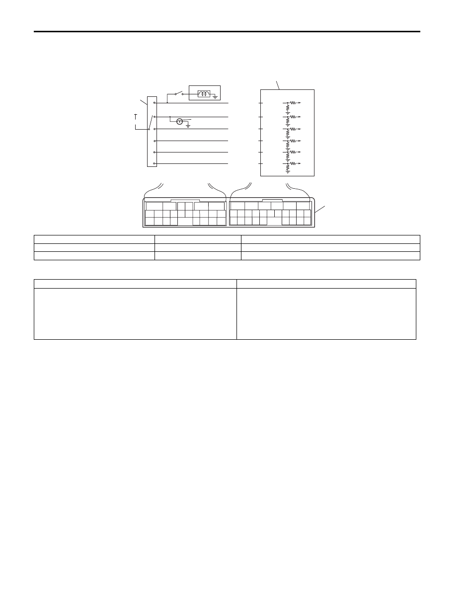
DTC P0705: Transmission Range Sensor Circuit Malfunction
S6JB0B5104020
Wiring Diagram
DTC Detecting Condition and Trouble Area
DTC Confirmation Procedure
1) Connect scan tool to DLC with ignition switch OFF.
2) Clear DTCs in TCM and ECM memories by using tool.
3) Start engine and shift select lever to “D” range.
4) Keep engine running at idle speed for 25 seconds or more.
5) Check DTC, pending DTC and freeze-frame data.
2
6
1
4
P
R
N
D
2
L
5
3
BLK/RED
RED
YEL/GRN
PNK/BLU
PNK/GRN
GRN/ORN
GRN/WHT
E93-20
E93-1
E93-8
E93-7
E93-19
E93-18
6
5
16 15 14 13 12 11
4 3
24 23
21
22
10 9
8
7
2
1
19
20
18 17
E92
17 16
26 25
15 14
6
5
3
4
2
13 12
23 22
24
11 10 9
21 20 19
8 7
18
1
E93
7
I5JB0A510020-01
1. TCM
4. Brake light switch
7. Terminal arrangement of TCM (viewed from harness side)
2. Transmission range sensor (switch)
5. Back-up light
3. From ignition switch
6. Shift lock solenoid
DTC Detecting Condition
Trouble Area
Multiple signal are inputted simultaneously for 2 seconds.
(1 driving cycle detection logic)
• Select cable maladjusted.
• Transmission range sensor (switch) maladjusted.
• Transmission range sensor (switch) or its circuit
malfunction.
• TCM

Automatic Transmission/Transaxle: 5A-43
DTC Troubleshooting
Step
Action
Yes
No
1
Was “A/T System Check” performed?
Go to Step 2.
Go to “A/T System
Check”.
2
Do you have SUZUKI scan tool?
Go to Step 3.
Go to Step 4.
3
Check transmission range sensor (switch) circuit for
operation
Check by using SUZUKI scan tool:
1) Connect SUZUKI scan tool to DLC with ignition switch
OFF.
2) Turn ignition switch ON and check transmission range
sensor signal (“P”, “R”, “N”, “D”, “3” or “L”) on display
when shifting select lever to each range.
Is applicable range indicated?
Intermittent trouble.
Check for intermittent
trouble referring to
“Intermittent and Poor
Connection Inspection
in Section 00”.
Go to Step 5
4
Check transmission range sensor (switch) circuit for
operation
Check by not using SUZUKI scan tool:
1) Turn ignition switch ON.
2) Check voltage at terminals “E93-1”, “E93-7”, “E93-8”,
“E93-18”, “E93-19” and “E93-20” respectively with select
lever shifted to each range.
Taking terminal “E93-1” as an example, is battery
voltage will be indicated only when shift lever is shifted to
“R” range and 0 V for other ranges as shown in table.
Check voltage at other terminals likewise, referring to
table.
Are check results satisfactory?
Intermittent trouble.
Check for intermittent
trouble referring to
“Intermittent and Poor
Connection Inspection
in Section 00”.
Go to Step 5.
5
Check transmission range sensor (switch) for
installation position
1) Check transmission range sensor (switch) for installation
position referring to “Transmission Range Sensor
Inspection and Adjustment”.
Is it adjusted correctly?
Go to Step 6.
Adjust transmission
range sensor (switch)
and recheck.
6
Check select cable for adjustment
1) Check select cable for adjustment referring to “Select
Is it adjusted correctly?
Go to Step 7.
Adjust select cable and
recheck.
7
Check transmission range sensor (switch)
1) Check transmission range sensor (switch) referring to
“Transmission Range Sensor Inspection and
Adjustment”.
Are check results satisfactory?
Transmission range
sensor circuit shorted to
power circuit or shorted
each other. If wires and
connections are OK,
substitute a known-
good TCM and recheck.
Replace transmission
range sensor (switch).
Terminal
E93-20
E93-1
E93-8
E93-7
E93-19
E93-18
Select lever
position
P
8 – 14 V
0 V
0 V
0 V
0 V
0 V
R
0 V
8 – 14 V
0 V
0 V
0 V
0 V
N
0 V
0 V
8 – 14 V
0 V
0 V
0 V
D or 4
0 V
0 V
0 V
8 – 14 V
0 V
0 V
3
0 V
0 V
0 V
0 V
8 – 14 V
0 V
L
0 V
0 V
0 V
0 V
0 V
8 – 14 V
Нет комментариевНе стесняйтесь поделиться с нами вашим ценным мнением.
Текст