Suzuki Grand Vitara JB627. Manual — part 215

5A-44 Automatic Transmission/Transaxle:
DTC P0707: Transmission Range Sensor Circuit Low
S6JB0B5104021
Wiring Diagram
Refer to “DTC P0705: Transmission Range Sensor Circuit Malfunction”.
DTC Detecting Condition and Trouble Area
DTC Confirmation Procedure
1) Connect scan tool to DLC with ignition switch OFF.
2) Clear DTCs in TCM and ECM memory by using scan tool.
3) Start engine and shift select lever to “D” range.
4) Start vehicle and increase vehicle speed to 50 km/h (31 mile/h) or more for 2 minutes.
5) Stop vehicle and turn ignition switch OFF.
6) Repeat Step 3) to 5) one time.
7) Stop vehicle.
8) Check DTC, pending DTC and freeze-frame data.
DTC Troubleshooting
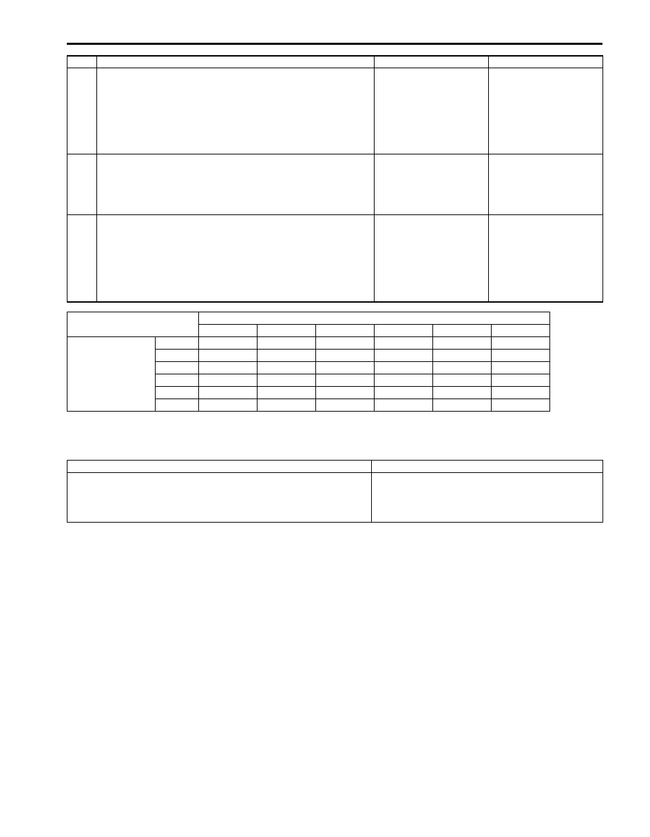
DTC Detecting Condition
Trouble Area
Transmission range switch signal (P, R, N, D, 3, L) is not
inputted for more than 2 seconds in the following condition.
• Vehicle speed is more than 30 km/h (19 mile/h).
• Engine speed is more than 1500 rpm.
(2 driving cycle detection logic)
• Select cable maladjusted.
• Transmission range sensor (switch) maladjusted.
• Transmission range sensor (switch) or its circuit
malfunction.
• TCM
Step
Action
Yes
No
1
Was “A/T System Check” performed?
Go to Step 2.
Go to “A/T System
Check”.
2
Do you have SUZUKI scan tool?
Go to Step 3.
Go to Step 4.
3
Check transmission range sensor (switch) circuit for
operation
Check by using SUZUKI scan tool:
1) Connect SUZUKI scan tool to DLC with ignition switch
OFF.
2) Turn ignition switch ON and check transmission range
signal (“P”, “R”, “N”, “D”, “3” or “L”) on display when
shifting select lever to each range.
Is applicable range indicated?
Intermittent trouble.
Check for intermittent
trouble to “Intermittent
and Poor Connection
Inspection in Section
00”.
Go to Step 5.
4
Check transmission range sensor (switch) circuit for
operation
Check without using SUZUKI scan tool:
1) Turn ignition switch ON.
2) Check voltage at terminals “E93-1”, “E93-8”, “E93-8”,
“E93-18”, “E93-19” and “E93-20” respectively with select
lever shifted to each range.
Taking terminal “E93-1” as an example, is battery
voltage will be indicated only when shift lever is shifted to
“R” range and 0 V for other ranges as shown in table.
Check voltage at other terminals likewise, referring to
table.
Are check results satisfactory?
Intermittent trouble.
Check for intermittent
trouble referring to
“Intermittent and Poor
Connection Inspection
in Section 00”.
Go to Step 5.
Automatic Transmission/Transaxle: 5A-45
DTC P0711: Transmission Fluid Temperature Sensor Range / Performance
S6JB0B5104022
DTC Detecting Condition and Trouble Area
DTC Confirmation Procedure
1) Connect scan tool to DLC with ignition switch OFF.
2) Clear DTCs in TCM and ECM memories by using scan tool.
3) Start engine and warm it up to normal operating temperature.
4) Shift select lever to “D” range.
5) Start vehicle and increase vehicle speed to 50 km/h (31 mile/h) or more with throttle position 10% for 30 minutes.
6) Stop vehicle and turn ignition switch OFF.
7) Repeat Step 3) to 4) one time.
8) Stop vehicle.
9) Check DTC, pending DTC and freeze-frame data.
5
Check transmission range sensor (switch) for
installation position
1) Check transmission range sensor (switch) for installation
position referring to “Transmission Range Sensor
Inspection and Adjustment”.
Is it adjusted correctly?
Go to Step 6.
Adjust transmission
range sensor (switch)
and recheck.
6
Check select cable for adjustment
1) Check select cable for adjustment referring to “Select
Is it adjusted correctly?
Go to Step 7.
Adjust select cable and
recheck.
7
Check transmission range sensor (switch)
1) Check transmission range sensor (switch) referring to
“Transmission Range Sensor Inspection and
Adjustment”.
Are check results satisfactory?
Transmission range
sensor circuit open or
shorted to ground. If
wires and connections
are OK, substitute a
known-good TCM and
recheck.
Replace transmission
range sensor (switch).
Step
Action
Yes
No
Terminal
E93-20
E93-1
E93-8
E93-7
E93-19
E93-18
Select lever
position
P
8 – 14 V
0 V
0 V
0 V
0 V
0 V
R
0 V
8 – 14 V
0 V
0 V
0 V
0 V
N
0 V
0 V
8 – 14 V
0 V
0 V
0 V
D or 4
0 V
0 V
0 V
8 – 14 V
0 V
0 V
3
0 V
0 V
0 V
0 V
8 – 14 V
0 V
L
0 V
0 V
0 V
0 V
0 V
8 – 14 V
DTC Detecting Condition
Trouble Area
Transmission fluid temperature sensor variation is less than
specified value even though engine was running for specified time
after engine start.
(2 driving cycle detection logic)
• Transmission fluid temperature sensor A or its
circuit.
• TCM
5A-46 Automatic Transmission/Transaxle:
DTC Troubleshooting
DTC P0712: Transmission Fluid Temperature Sensor “A” Circuit Low
S6JB0B5104023
Wiring Diagram
DTC Detecting Condition and Trouble Area
DTC Confirmation Procedure
1) Connect scan tool to DLC with ignition switch OFF.
2) Clear DTCs in TCM and ECM memories by using scan tool.
3) Start engine.
4) Keep engine running at idle speed for 1 minute or more.
5) Check DTC, pending DTC and freeze-frame data.
Step
Action
Yes
No
1
Was “A/T System Check” performed?
Go to Step 2.
Go to “A/T System
Check”.
2
Inspection transmission fluid temperature sensor A
1) Inspection transmission fluid temperature sensor A
referring to “Transmission Fluid Temperature Sensor
Inspection”.
Is check result satisfactory?
Intermittent trouble or
faulty TCM. Check for
intermittent trouble
referring to “Intermittent
and Poor Connection
Inspection in Section
00”. If OK, substitute a
known-good TCM and
recheck.
Replace valve body
harness including
transmission fluid
temperature sensor A
referring to
“Transmission Fluid
Temperature Sensor
Removal and
Installation”.
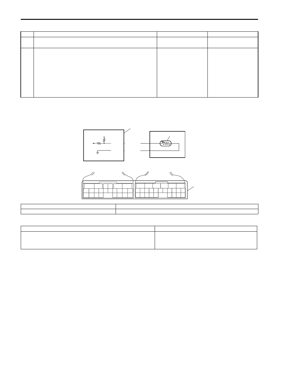
5V
E92-11
E92-12
YEL/BLK
ORN
2
1
3
6
5
16 15 14 13 12 11
4 3
24 23
21
22
10 9
8
7
2
1
19
20
18 17
E92
17 16
26 25
15 14
6
5
3
4
2
13 12
23 22
24
11 10 9
21 20 19
8 7
18
1
E93
I6JB01510012-01
1. Transmission fluid temperature sensor A
3. Terminal arrangement of TCM connector (viewed from harness side)
2. TCM
DTC Detecting Condition
Trouble Area
Transmission temperature sensor terminal voltage is less than
0.05 V for 10 seconds minutes or more after ignition switch ON.
(1 driving cycle detection logic)
• Transmission fluid temperature sensor A or its
circuit.
• TCM

Automatic Transmission/Transaxle: 5A-47
DTC Troubleshooting
DTC P0713: Transmission Fluid Temperature Sensor “A” Circuit High
S6JB0B5104024
Wiring Diagram
Refer to “DTC P0712: Transmission Fluid Temperature Sensor “A” Circuit Low”.
DTC Detecting Condition and Trouble Area
DTC Confirmation Procedure
1) Connect scan tool to DLC with ignition switch OFF.
2) Clear DTCs in TCM and ECM memories by using scan tool.
3) Start engine.
4) Start vehicle and increase vehicle speed to about 40 km/h (25 mile/h) for 20 minutes or more.
5) Stop vehicle.
6) Check DTC, pending DTC and freeze-frame data.
Step
Action
Yes
No
1
Was “A/T System Check” performed?
Go to Step 2.
Go to “A/T System
Check”.
2
Check transmission fluid temperature sensor A circuit
for ground short
1) Turn ignition switch OFF.
2) Disconnect TCM connectors from TCM.
3) Check for proper connection to transmission fluid
temperature sensor A at terminal “E92-11” and “E92-12”.
4) If OK, check continuity between terminal “E92-11” of
disconnected harness side TCM connector and ground.
Is continuity indicated?
“Transmission fluid
temperature sensor A
signal” circuit shorted to
ground. If circuit is OK,
go to Step 3.
Go to Step 3.
3
Inspection transmission fluid temperature sensor A
1) Inspection transmission fluid temperature sensor A
referring to “Transmission Fluid Temperature Sensor
Inspection”.
Is check result satisfactory?
Intermittent trouble or
faulty TCM. Check for
intermittent trouble
referring to “Intermittent
and Poor Connection
Inspection in Section
00”. If OK, substitute a
known-good TCM and
recheck.
Replace valve body
harness including
transmission fluid
temperature sensor A
referring to
“Transmission Fluid
Temperature Sensor
Inspection”.
DTC Detecting Condition
Trouble Area
Transmission temperature sensor terminal voltage is less than
4.89 V under vehicle condition shown in the following.
• Ignition switch is turned on for 15 minutes or more
• Engine coolant temperature is more than 50
°C (122 °F)
(1 driving cycle detection logic)
• Transmission fluid temperature sensor or its
circuit.
• TCM
Нет комментариевНе стесняйтесь поделиться с нами вашим ценным мнением.
Текст