Suzuki Grand Vitara JB627. Manual — part 138
3A-3 Drive Shaft / Axle: Front
Front Drive Shaft Assembly Removal and
Installation
S6JB0B3116003
Removal
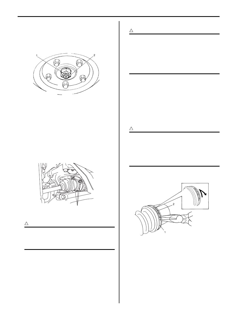
1) Undo caulking (1) and remove drive shaft nut (2).
2) Hoist vehicle and remove wheel.
3) Drain front differential oil.
4) Disconnect tie-rod end from steering knuckle
referring to “Steering Knuckle Removal and
Installation in Section 2B”.
5) Remove stabilizer joint from stabilizer bar.
6) Remove brake hose mounting bolt.
7) Remove suspension control arm referring to
“Suspension Control Arm Removal and Installation
in Section 2B”.
8) Remove front drive shaft flange nuts (1).
9) Remove drive shaft assembly from front differential.
CAUTION
!
To prevent breakage of boots (wheel side and
differential side), do not contact them with
other parts when removing drive shaft
assembly.
Installation
CAUTION
!
• Be careful not to damage oil seals and
boots when installing drive shaft.
• Do not hit joint boot with hammer.
Inserting joint only by hands is allowed.
• Make sure that differential side joint is
inserted fully and its snap ring is seated as
it was.
Install drive shaft assembly by reversing removal
procedure and noting the following points.
• Tighten each bolts and nuts to the specified torque
referring to “Front Drive Shaft Components: Front”
and “Front Suspension Construction in Section 2B”.
Front Drive Shaft Disassembly and Assembly
S6JB0B3116004
Disassembly
CAUTION
!
• Disassembly of wheel side joint assembly
is not allowed. If any noise or damage
exists in it, replace it as assembly.
• Do not disassemble tripod joint spider. If
any malcondition is found in it, replace it
as differential side joint assembly.
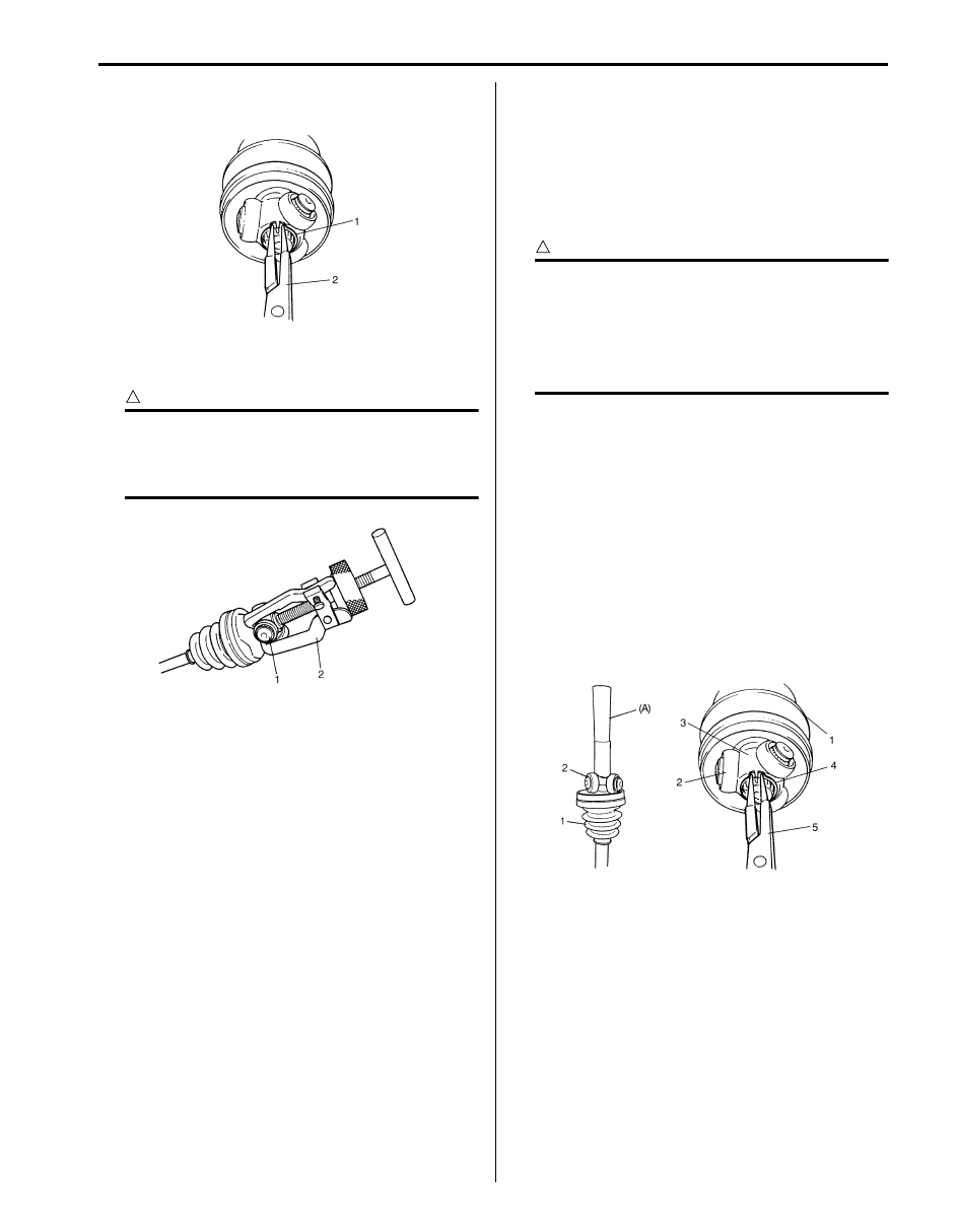
1) Draw hooks (2) of boot big band together and
remove differential side boot big band (1).
I5JB0A311003-01
1
I5JB0A311004-01
I5JB0A311005-01
Drive Shaft / Axle: Front 3A-4
2) Wipe off grease from shaft and take off snap ring (1)
using snap ring plier (2).
3) Remove tripod joint spider (1) using 3 arms puller
(2).
CAUTION
!
To prevent any problem caused by washing
solution, do not wash tripod joint except its
housing. Degreasing of tripod joint with cloth
is allowed.
4) Remove differential side boot small band, and then
pull out differential side boot from shaft.
Assembly
Judging from abnormality noted before disassembly and
what is found through visual check of component parts
after disassembly, prepare replacing parts and proceed
to reassembly.
Make sure that tripod joint housing is washed thoroughly
and air dried.
Replace boot with new one.
CAUTION
!
• Do not wash boots in degreaser such as
gasoline or kerosene. etc. Washing in
degreaser causes deterioration of boot.
• To ensure full performance of joint as
designed, apply grease of specified
volume and color to joint.
1) Wash disassembled parts (except boots). After
washing, dry parts completely by blowing air.
2) Clean boots with cloth.
3) Set new differential side small band and new
differential side boot (1) on shaft temporarily, and
then apply grease to tripod joint (2). Use specified
grease in tube included in spare parts.
4) Install tripod joint spider (3) on shaft using special
tool with hammer, directing its chamfered spline
toward wheel side, and then fasten it with new snap
ring (4) using snap ring plier (5).
Special tool
(A): 09913–80113
I5JB0A311008-01
I3RH0A311004-01
I5JB0A311009-01
3A-5 Drive Shaft / Axle: Front
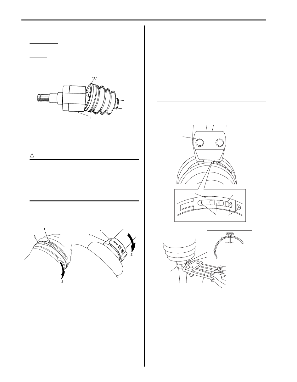
5) Apply grease (including in spare parts) to inside of
tripod joint housing (1), joint it with tripod joint.
Grease color
“A”: Yellow
Amount
“A”: 127 – 137 g (4.5 – 4.8 oz) (right side)
“A”: 170 – 180 g (6.0 – 6.3 oz) (left side)
6) Fit boot to grooves of shaft and housing.
7) Insert screw driver into boot and allow air to enter
boot so that air pressure in boot becomes the same
as atmospheric pressure.
CAUTION
!
• Bend each boot band against forward
rotation.
• Do not squeeze or distort boot when
fastening it with bands. Distorted boot
caused by squeezing air may reduce its
durability.
8) Place differential side boot new big band (3) and new
small band (4) onto boot putting band outer end (1)
against forward rotation (2) as shown in figure.
9) Fasten differential side boot big band.
• For differential side boot big band
Fasten band (1) by drawing hooks (2) with special
tool and engage hooks (3) in slot and window (4).
Special tool
(A): 09943–57010
• For differential side boot small band
Fasten band (5) securely using special tool.
NOTE
Fasten boot small band securely until
complete contact “a” is obtained.
Special tool
(A): 09943–57010
I4RS0B310003-01
I5JB0A311006-01
(A)
1
4
2
3
(B)
5
“a”
I5JB0A311007-03
Drive Shaft / Axle: Front 3A-6
Specifications
Tightening Torque Specifications
S6JB0B3117001
NOTE
The specified tightening torque is also described in the following.
“Front Drive Shaft Components: Front”
Reference:
For the tightening torque of fastener not specified in this section, refer to “Fastener Information in Section 0A”.
Special Tools and Equipment
Recommended Service Material
S6JB0B3118001
NOTE
Required service material is also described in the following.
“Front Drive Shaft Components: Front”
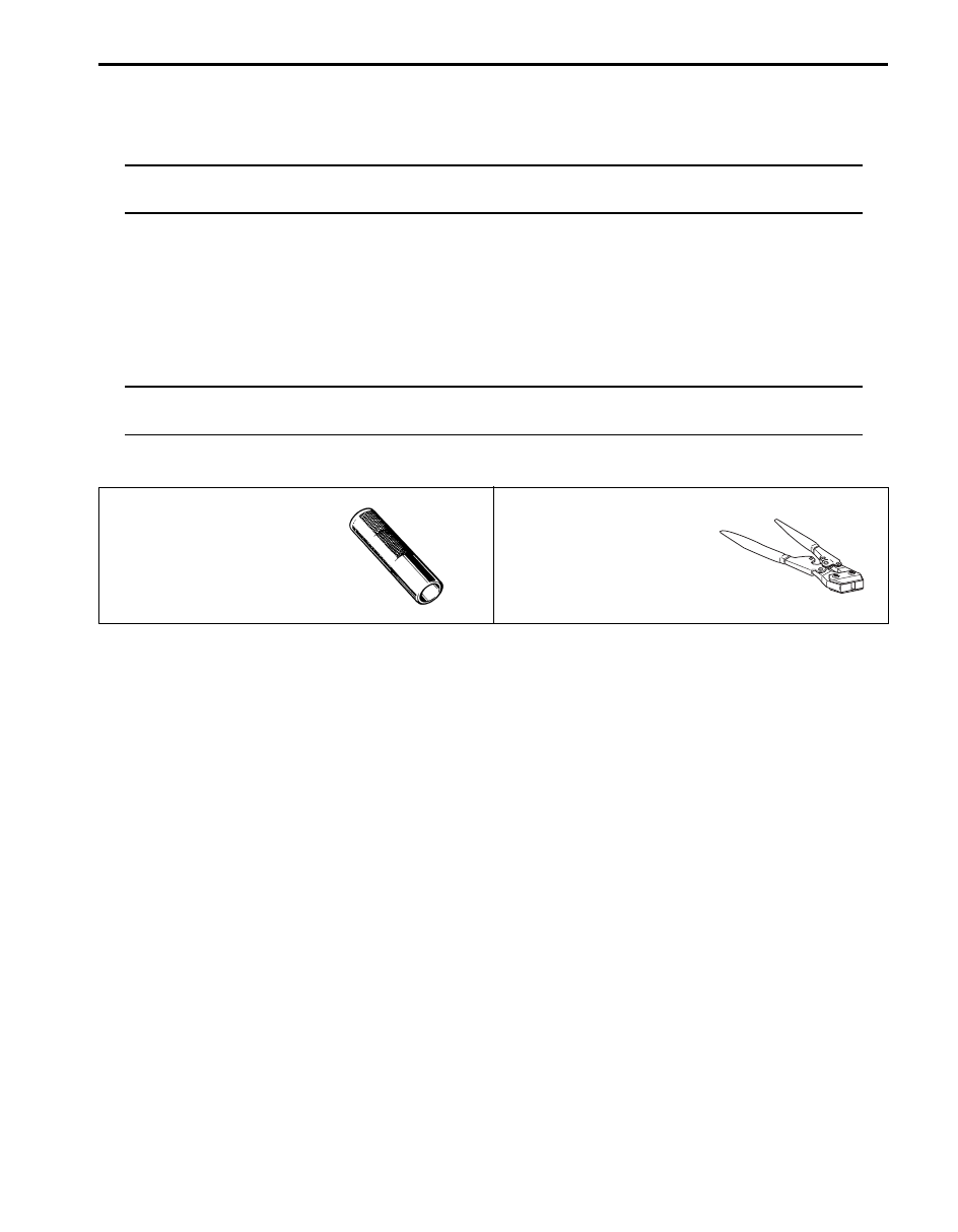
Special Tool
S6JB0B3118002
09913–80113
09943–57010
Bearing installer
Band compressor
Нет комментариевНе стесняйтесь поделиться с нами вашим ценным мнением.
Текст