Suzuki Grand Vitara JB627. Manual — part 139
3A-7 Drive Shaft / Axle: Rear
Rear
General Description
Rear Drive Shaft Construction
S6JB0B3121001
Refer to “Front Drive Shaft Construction: Front”.
Repair Instructions
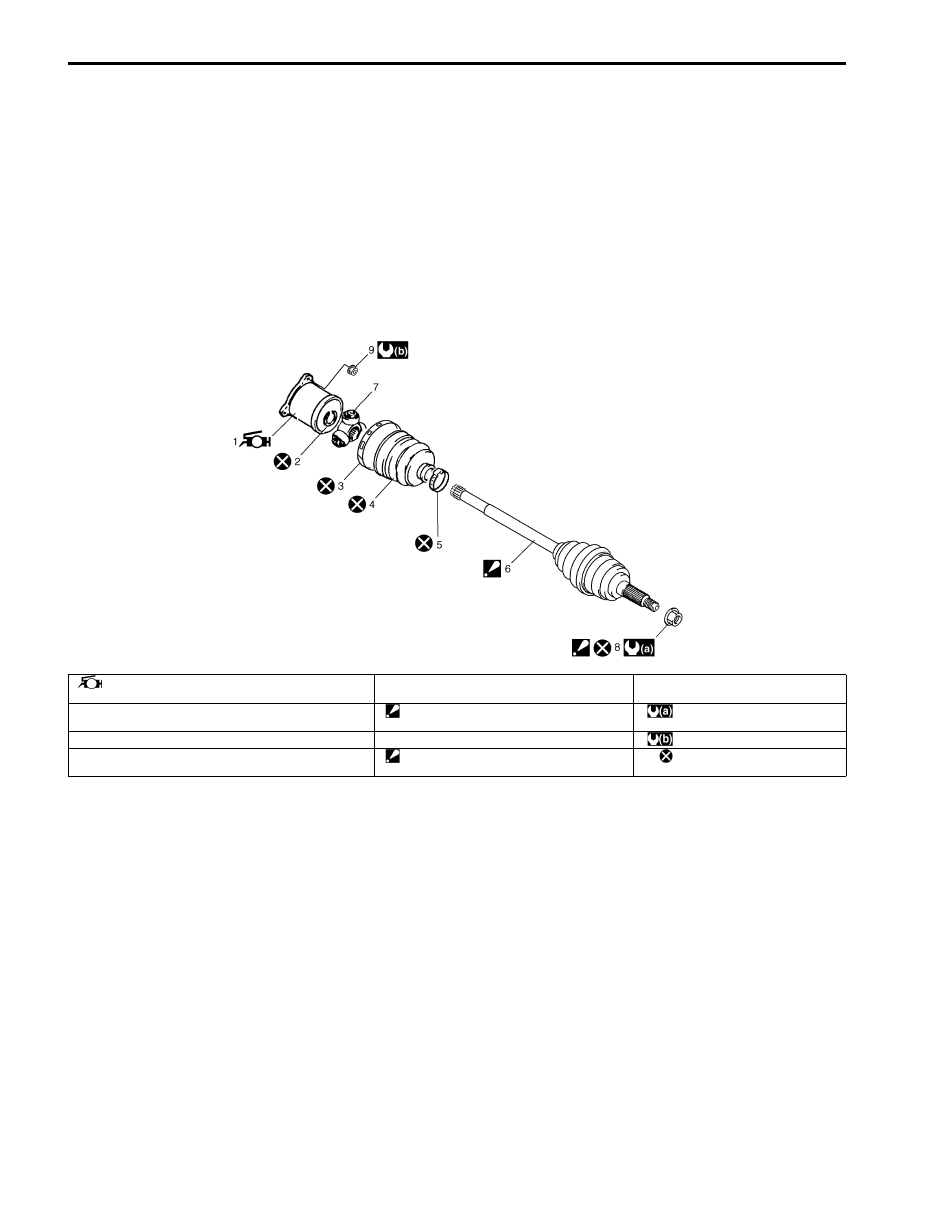
Rear Drive Shaft Components
S6JB0B3126001
I5JB0A312001-02
1. Differential side joint (Constant velocity tripod joint)
: Apply yellow grease included in spare part to joint.
5. Boot band (Small)
9. Rear drive shaft flange nut
2. Snap ring
6. Wheel side joint (Constant velocity ball joint)
: Never disassemble.
: 220 N
⋅m (22.0 kgf-m, 159.5 lb-ft)
3. Boot band (Large)
7. Tripod joint spider
: 80 N
⋅m (8.0 kgf-m, 58.0 lb-ft)
4. Boot (Differential side)
8. Drive shaft nut
: After tightening nut, caulk nut securely.
: Do not reuse.
Drive Shaft / Axle: Rear 3A-8
Rear Drive Shaft Assembly Removal and
Installation
S6JB0B3126002
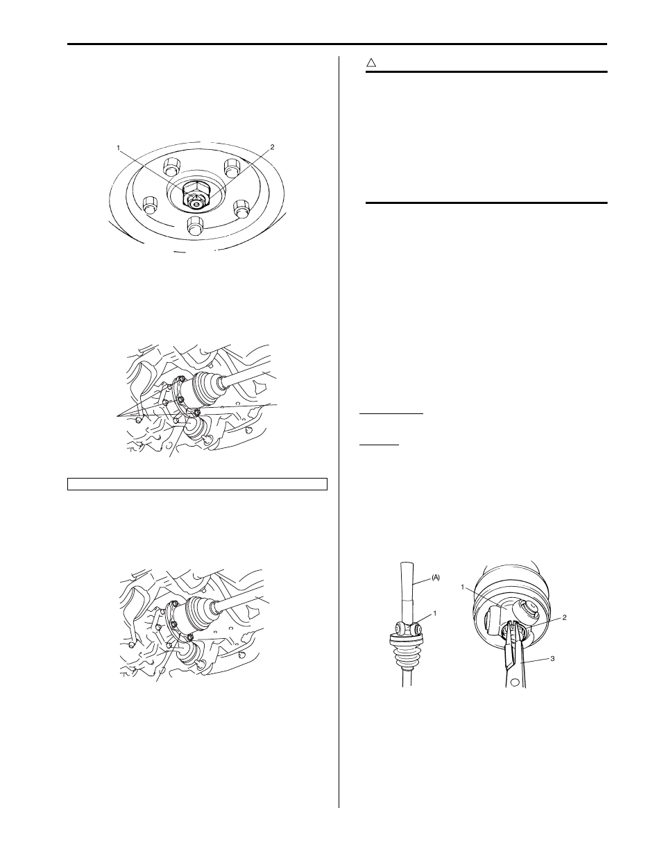
Removal
1) Undo caulking (1) of drive shaft nut (2) and then
remove drive shaft nut.
2) Hoist vehicle and remove wheel.
3) Give match mark rear drive shaft flange (3) and rear
drive shaft (4) as shown in figure, and then remove
rear drive shaft flange nuts (1), and then remove rear
drive shaft.
Installation
Install drive shaft assembly by reversing removal
procedure and noting the following points.
• Install rear drive shaft (1) aligning match marks (2).
CAUTION
!
• Protect oil seals and boots from any
damage, preventing them form
unnecessary contact while installing drive
shaft.
• Do not hit joint boot with hammer.
Inserting joint only by hands is allowed.
• Make sure that differential side joint is
inserted fully and its snap ring is seated as
it was.
• Tighten each nuts to specified torque referring to
“Rear Drive Shaft Components: Rear”.
Rear Drive Shaft Disassembly and Assembly
S6JB0B3126003
Disassembly
Refer to “Front Drive Shaft Disassembly and Assembly:
Front”.
Assembly
Assemble rear drive shaft assembly referring to “Front
Drive Shaft Disassembly and Assembly: Front” and
noting the following points which are different from that
of the front drive shaft assembly.
• Apply grease to differential side joint.
Grease color
: Yellow
Amount
: 197 – 207 g (6.9 – 7.3 oz)
• Install tripod joint spider (1) on shaft by using special
tool with hammer, directing its chamfered spline
toward wheel side, and then fasten it with new snap
ring (2) using snap ring plier (3).
Special tool
(A): 09913–84510
2. Match mark
I5JB0A311003-01
1
3
2
4
I5JB0A312002-02
2
1
I5JB0A312003-01
I5JB0A312004-03

3A-9 Drive Shaft / Axle: Rear
Specifications
Tightening Torque Specifications
S6JB0B3127001
NOTE
The specified tightening torque is also described in the following.
“Rear Drive Shaft Components: Rear”
Reference:
For the tightening torque of fastener not specified in this section, refer to “Fastener Information in Section 0A”.
Special Tools and Equipment
Recommended Service Material
S6JB0B3128001
NOTE
Required service material is also described in the following.
“Rear Drive Shaft Components: Rear”
Special Tool
S6JB0B3128002
09913–84510
Bearing installer
)

Differential: Front 3B-1
Driveline / Axle
Differential
Front
General Description
Front Differential Construction
S6JB0B3211001
The differential assembly uses a hypoid bevel pinion and gear.
The differential assembly is decisive in that the drive power is concentrated there. Therefore, use of genuine parts and
specified torque is compulsory. Further, because of sliding tooth meshing with high pressure between bevel pinion and
gear, it is mandatory to lubricate them by hypoid gear oil.
Diagnostic Information and Procedures
Front Differential Symptom Diagnosis
S6JB0B3214001
Condition
Possible cause
Correction / Reference Item
Gear noise
Deteriorated or water mixed lubricant
Repair and replenish referring to “Front
Differential Oil Change: Front”.
Inadequate or insufficient lubricant
Repair and replenish referring to “Front
Differential Oil Change: Front”.
Maladjusted backlash between drive
bevel pinion and gear
Adjust as prescribed referring to “Front
Differential Assembly Disassembly and
Reassembly: Front”.
Improper tooth contact in the mesh
between drive bevel pinion and gear
Adjust or replace referring to “Front Differential
Assembly Disassembly and Reassembly:
Front”.
Loose drive bevel gear securing bolts
Replace or retighten referring to “Front
Differential Assembly Disassembly and
Reassembly: Front”.
Damaged differential gear(s) or
differential pinion(s)
Replace referring to “Front Differential
Inspection: Front”.
Bearing noise
(Constant noise) Deteriorated or water
mixed lubricant
Repair and replenish referring to “Front
Differential Oil Change: Front”.
(Constant noise) Inadequate or
insufficient lubricant
Repair and replenish referring to “Front
Differential Oil Change: Front”.
(Noise while coasting) Damaged
bearing(s) of drive bevel pinion
Replace referring to “Front Differential
Inspection: Front”.
(Noise while turning) Damaged
differential side bearing(s) or axle
bearing(s)
Replace referring to “Front Differential
Inspection: Front”.
Oil leakage
Clogged breather plug
Clean.
Worn or damaged oil seal
Replace.
Excessive oil
Adjust oil level referring to “Front Differential
Oil Change: Front”.
Loose differential carrier bolts
Replace or retighten.
Нет комментариевНе стесняйтесь поделиться с нами вашим ценным мнением.
Текст