Suzuki Grand Vitara JB627. Manual — part 22

1A-37 Engine General Information and Diagnosis:
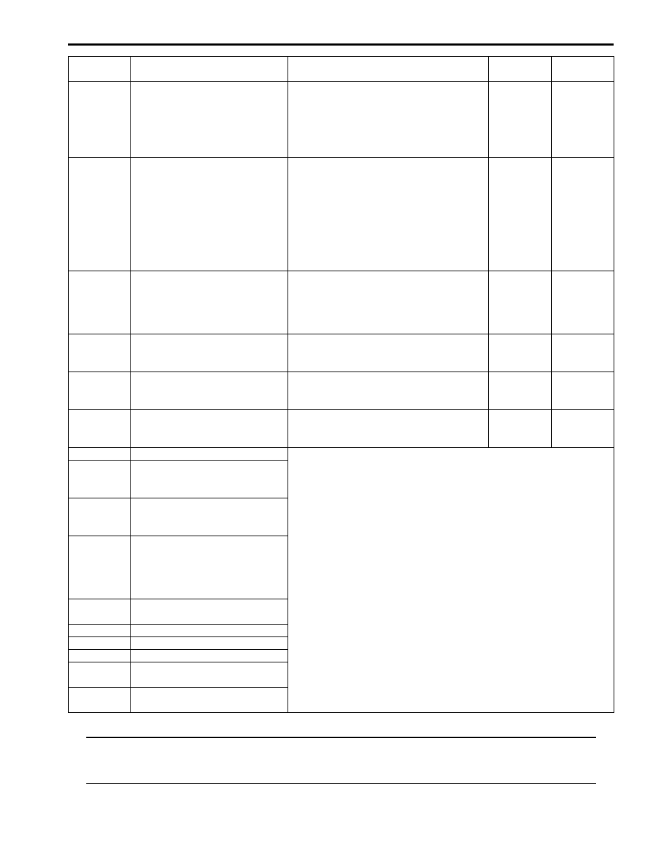
P2239
O2 Sensor Positive Current
Control Circuit High (Bank 1
Sensor 1)
Circuit voltage of A/F sensor (+) terminal is
higher than 3.5 V with engine running
1 driving
cycle
1 driving
cycle
P2240
O2 Sensor Positive Current
Control Circuit / Open (Bank 2
Sensor 1)
Impedance of A/F sensor element is
higher than 250
Ω for more than 5 sec
even though A/F sensor heater is turned
ON with engine running.
1 driving
cycle
1 driving
cycle
P2241
O2 Sensor Positive Current
Control Circuit Low (Bank 2
Sensor 1)
Circuit voltage of A/F sensor (+) terminal is
lower than 0.4 V or A/F sensor circuit is
shorted between (+) terminal wire and (–)
terminal wire with engine running.
1 driving
cycle
1 driving
cycle
P2242
O2 Sensor Positive Current
Control Circuit High (Bank 2
Sensor 1)
Circuit voltage of A/F sensor (+) terminal is
higher than 3.5 V with engine running.
1 driving
cycle
1 driving
cycle
P2252
O2 Sensor Negative Current
Control Circuit Low (Bank 1
Sensor 1)
Circuit voltage of A/F sensor (–) terminal is
lower than 0.4 V with engine running.
1 driving
cycle
1 driving
cycle
P2253
O2 Sensor Negative Current
Control Circuit High (Bank 1
Sensor 1)
Circuit voltage of A/F sensor (–) terminal is
higher than 3.5 V with engine running.
1 driving
cycle
1 driving
cycle
P2255
O2 Sensor Negative Current
Control Circuit Low (Bank 2
Sensor 1)
Circuit voltage of A/F sensor (–) terminal is
lower than 0.4 V with engine running.
1 driving
cycle
1 driving
cycle
P2256
O2 Sensor Negative Current
Control Circuit High (Bank 2
Sensor 1)
Circuit voltage of A/F sensor (–) terminal is
higher than 3.5 V with engine running.
1 driving
cycle
1 driving
cycle
P2627
O2 Sensor Pumping Current
Trim Circuit Low (Bank 1 Sensor
1)
Output voltage of A/F sensor adjusting
resister is less than 0.1 V for more than 4
sec continuously with engine running.
1 driving
cycle
1 driving
cycle
P2628
O2 Sensor Pumping Current
Trim Circuit High (Bank 1 Sensor
1)
Output voltage of A/F sensor adjusting
resister is more than 5 V for more than 4
sec continuously with engine running.
1 driving
cycle
1 driving
cycle
P2630
O2 Sensor Pumping Current
Trim Circuit Low (Bank 2 Sensor
1)
Output voltage of A/F sensor adjusting
resister is less than 0.1 V for more than 4
sec continuously with engine running.
1 driving
cycle
1 driving
cycle
P2631
O2 Sensor Pumping Current
Trim Circuit High (Bank 2 Sensor
1)
Output voltage of A/F sensor adjusting
resister is more than 5 V for more than 4
sec continuously with engine running.
1 driving
cycle
1 driving
cycle
O2 Sensor Circuit Range/
Performance (Bank 1 Sensor 1)
Amplitude index of A/F sensor signal
between rich and lean is more than 1.3 or
less than 0.7 while A/F (fuel trim) is shifted
from rich to lean and lean to rich with
specified diagnosis frequency under
specified running.
2 driving
cycles
2 driving
cycles
O2 Sensor Circuit Range/
Performance (Bank 1 Sensor 2)
Circuit voltage of HO2S (bank-1) signal is
less than 0.35 V while A/F (fuel trim) is
shifted from rich to lean and lean to rich
with specified diagnosis frequency under
specified running, or Circuit voltage of
HO2S (bank-1) signal is more than 0.2 V
for more than 4 sec even though vehicle is
running with fuel cut mode below 4000
rpm.
2 driving
cycles
2 driving
cycles
DTC No.
Detected item
Detecting condition
(DTC will set when detecting:)
DTC
MIL
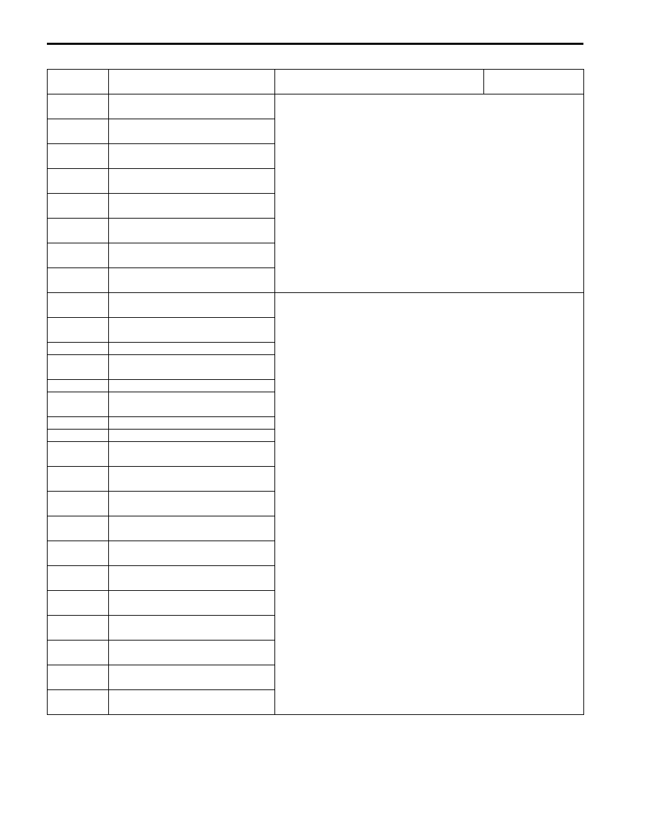
Engine General Information and Diagnosis: 1A-38
NOTE
MIL blinks or lights up. Refer to “DTC P0300/P0301/P0302/P0303/P0304/P0305/P0306: Random Misfire/
Cylinder 1 Misfire/Cylinder 2 Misfire/Cylinder 3 Misfire/Cylinder 4 Misfire/Cylinder 5 Misfire/Cylinder 6
Misfire Detected” for details.
O2 Sensor Circuit Range/
Performance (Bank 2 Sensor 1)
Amplitude index of A/F sensor signal
between rich and lean is more than 1.3 or
less than 0.7 while A/F (fuel trim) is shifted
from rich to lean and lean to rich with
specified diagnosis frequency under
specified running.
2 driving
cycles
2 driving
cycles
O2 Sensor Circuit Range/
Performance (Bank 2 Sensor 2)
Circuit voltage of HO2S (bank-2) signal is
less than 0.35 V while A/F (fuel trim) is
shifted from rich to lean and lean to rich
with specified diagnosis frequency under
specified running, or Circuit voltage of
HO2S (bank-2) signal is more than 0.2 V
for more than 4 sec even though vehicle is
running with fuel cut mode below 4000
rpm.
2 driving
cycles
2 driving
cycles
U0073
Control Module Communication
Bus Off
Transmission error that is inconsistent
between transmission data and
transmission monitor (CAN bus monitor)
data is detected more than 7 times
continuously.
1 driving
cycle
Not
applicable
U0101 Lost Communication with TCM
Reception error of communication data for
TCM is detected for longer than specified
time continuously.
1 driving
cycle
1 driving
cycle
U0121
Lost Communication With
Electronic Stability Program /
ABS Control Module
Reception error of communication data for
ABS or ESP
® control module is detected
for longer than specified time continuously.
1 driving
cycle
1 driving
cycle
U0140
Lost Communication With Body
Control Module
Reception error of communication data for
BCM is detected for longer than specified
time continuously.
1 driving
cycle
Not
applicable
P1614
Transponder Response Error
Refer to “Diagnostic Trouble Code (DTC) Table in Section 10C”.
P1615
ID Code Does Not Registered
(Vehicle Equipped with Keyless
Start System Only)
P1616
Different Registration ID Codes
(Vehicle Equipped with Keyless
Start System Only)
P1618
CAN Communication Error
(Reception Error for Keyless
Start Control Module) (Vehicle
Equipped with Keyless Start
System Only)
P1621
Immobilizer Communication Line
Error
P1622
EEPROM Error
P1623
Unregistered Transponder
P1625
Immobilizer Antenna Error
P1636
Immobilizer Information
Registration Failure
P1638
Immobilizer Information
Mismatched
DTC No.
Detected item
Detecting condition
(DTC will set when detecting:)
DTC
MIL
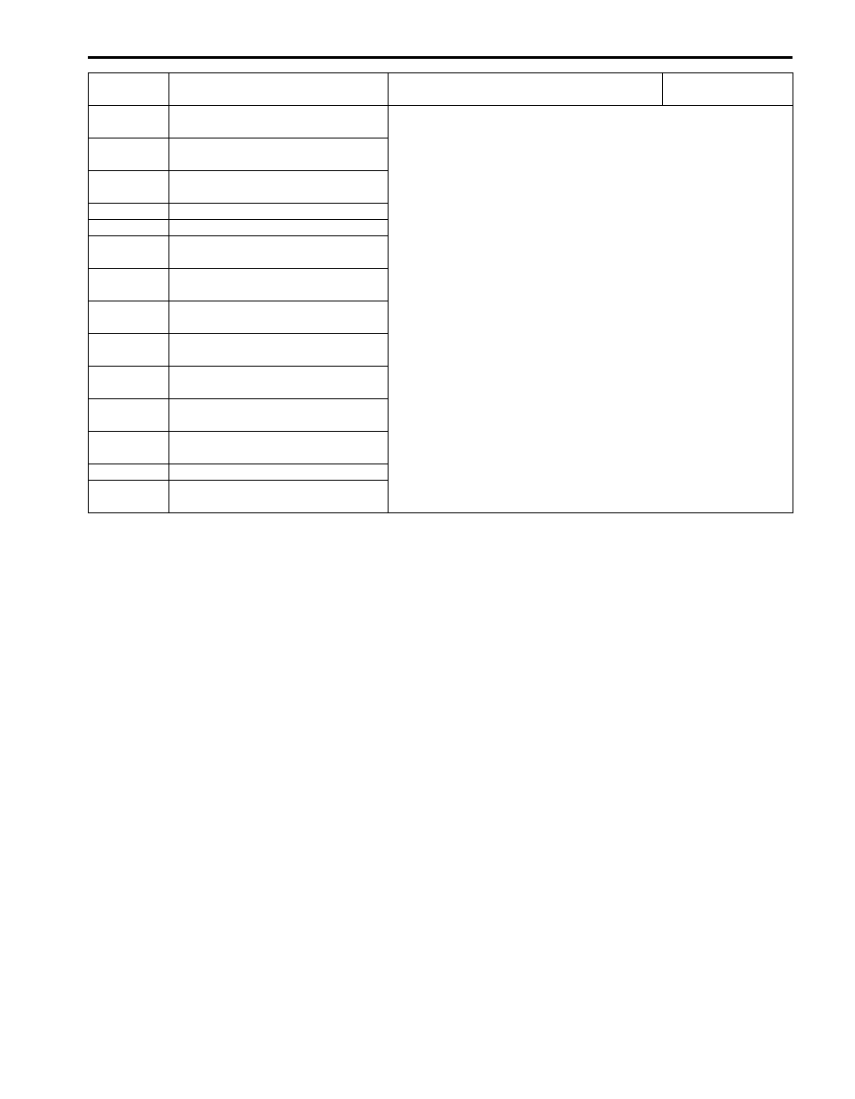
1A-39 Engine General Information and Diagnosis:
For A/T System (Only OBD Generic Scan Tool Is Displayed on the Following DTC(s) at the Same Time)
DTC No.
Detecting Item
Detecting Condition
(DTC will set when detecting)
MIL
Transmission Range Sensor Circuit
Malfunction (PRNDL Input)
Refer to “DTC Table in Section 5A”.
Transmission Range Sensor Circuit
Low
P0711
Transmission Fluid Temperature
Sensor Range / Performance
Transmission Fluid Temperature
Sensor “A” Circuit Low
Transmission Fluid Temperature
Sensor “A” Circuit High
Input / Turbine Speed Sensor
Circuit No Signal
Output Speed Sensor Circuit No
Signal
Torque Converter Clutch Circuit
Performance or Stuck Off
Torque Converter Clutch Circuit
Stuck On
Refer to “DTC Table in Section 5A”.
Shift Solenoid “A” Performance or
Stuck Off
P0752 Shift Solenoid “A” Stuck On
Shift Solenoid “B” Performance or
Stuck Off
P0757 Shift Solenoid “B” Stuck On
Shift Solenoid “E” Performance or
Stuck Off
P0772 Shift Solenoid “E” Stuck On
P0781 1-2 Shift
Pressure Control Solenoid “C”
Stuck On
Pressure Control Solenoid “A”
Control Circuit Low
Pressure Control Solenoid “A”
Control Circuit High
Pressure Control Solenoid “B”
Control Circuit Low
Pressure Control Solenoid “B”
Control Circuit High
Pressure Control Solenoid “C”
Control Circuit Low
Pressure Control Solenoid “C”
Control Circuit High
Shift Solenoid “A” Control Circuit
Low
Shift Solenoid “A” Control Circuit
High
Shift Solenoid “B” Control Circuit
Low
Shift Solenoid “B” Control Circuit
High
Engine General Information and Diagnosis: 1A-40
Shift Solenoid “E” Control Circuit
Low
Refer to “DTC Table in Section 5A”.
Shift Solenoid “E” Control Circuit
High
Internal Control Module Memory
Check Sum Error
P1703 CAN Invalid Data – TCM
P1723 Range Select Switch Malfunction
4WD Low switch circuit malfunction
(Short)
4WD Low switch circuit malfunction
(Open)
Transmission Fluid Temperature
Sensor “B” Circuit Low
Transmission Fluid Temperature
Sensor “B” Circuit High
Torque Converter Clutch Circuit
High
Torque Converter Clutch Circuit
Low
U0073
Control Module Communication
Bus OFF
U0100 Lost Communication With ECM
U0140
Lost Communication With Body
Control Module
DTC No.
Detecting Item
Detecting Condition
(DTC will set when detecting)
MIL
Нет комментариевНе стесняйтесь поделиться с нами вашим ценным мнением.
Текст