Suzuki Grand Vitara JB627. Manual — part 276
7B-20 Air Conditioning System:
Visual Inspection
S6JB0B7204007
Visually check the following parts and systems.
A/C System Performance Inspection
S6JB0B7204008
1) Confirm that vehicle and environmental conditions
are as follows.
• Vehicle is put indoors.
• Ambient air temperature is within 15 – 35
°C (59 –
95
°F).
• Relative humidity is within 30 – 70%.
• There is no wind indoors.
• HVAC unit is normal condition.
• There is no air leakage from air ducts.
• Condenser fins are clean.
• Are filter is not clogged with dirt and dust.
• Battery voltage is 12 V or more.
• Radiator cooling fan operates normally.
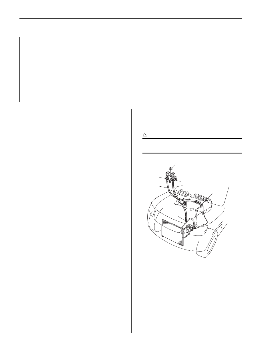
2) Make sure that high pressure valve (1) and low
pressure valve (2) of manifold gauge (3) are firmly
closed.
3) Connect high pressure charging hose (4) to high
pressure service valve (5) on vehicle, and connect
low pressure charging hose (6) to low pressure
service valve (7) on vehicle.
4) Bleed the air in charging hoses by loosening their
respective nuts on manifold gauge, utilizing the
refrigerant pressure. When a hiss is heard,
immediately tighten nut.
CAUTION
!
Do not interchange high and low pressure
charging hoses by mistake.
Inspection Item
Correction
• Refrigerant ---- leakage and amount
• A/C pipe or hose ---- disconnection, looseness and
deterioration
• A/C compressor drive belt ---- looseness and damage
• Battery ---- fluid level and corrosion of terminal
• Connectors of electric wire harness ---- disconnection and
friction
• Fuses ---- burning
• Parts ---- installation and damage
• Other parts that can be checked visually
Refer to “A/C Compressor Drive Belt Inspection
and Adjustment”.
3
7
4
1
2
6
5
I5JB0A720010-01

Air Conditioning System: 7B-21
5) Warm up engine to normal operating temperature
(engine coolant temperature at 80 – 90
°C (176 –
194
°F)) and keep it at specified idle speed.
6) Operate A/C at the following conditions.
• A/C switch at ON position
• Blower speed selector at max position
• Air flow selector at “VENT” position
• Temperature selector at max cool position
• Vehicle door at all open
• Air inlet door at recirculation position
7) Wait for ten minutes to stabilize A/C operation.
8) Keep all windows, doors and engine food open.
9) With about 20 mm (0.8 in.) of dry bulb thermometer
(1) put right in front of center ventilation louver and a
wet and dry bulb thermometer (2) near air inlet (3) of
HVAC unit.
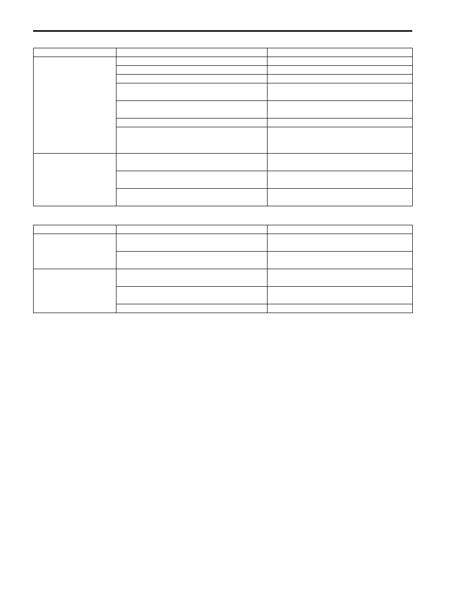
10) Check for each pressure of low side and high side if it is within shaded range of graph. If each gauge reading is out
of specified pressure, correct defective part referring to the table.
Low side and high side pressure example, gauges should read as follows when ambient temperature is 30
°C (86 °F)
Pressure on high pressure gauge (HI): 1340 – 1670 kPa (13.4 – 16.7 kg/cm
2
, 191 – 237 psi)
Pressure on high pressure gauge (LO): 280 – 390 kPa (2.8 – 3.9 kg/cm
2
, 40 – 55 psi)
NOTE
Pressure registered on gauge varies with ambient temperature. Therefore, use the graphs when
determining if pressures are normal or not.
1
3
2
I5JB0A720011-01
14.2
28.4
Pressure of Lo
Pressure Gauge
22
312.9
2200
0
1
2
3
30
70
30
70
%
4
5
6
7
8
9
10
11
12
13
14
15
16
17
18
19
21
298.7
2100
20
42.7
56.9
71.1
85.3
99.5
113.8
128.0
142.2
151.4
170.6
184.9
199.1
213.3
227.5
241.7
256.0
270.2
284.4
100
200
300
400
500
600
700
800
900
1000
1100
1200
1300
1400
1500
1600
1700
1800
1900
2000
25
30
35
77
86
95
psi
kPa kg/cm
2
Ambient Temperature
C
F
w
Pressure of High Pressure
Gauge
“A”
“B”
“C”
“D”
Humidity
Acceptab
le
range
Acceptab
le range
I6JB01720005-02
7B-22 Air Conditioning System:
High pressure gauge
Low pressure gauge
Condition
Possible Cause
Correction
Pressure is higher than
acceptable range
(“A” area)
Refrigerant overcharged
Recharge.
Expansion valve frozen or clogged
Check expansion valve.
Clogged refrigerant passage of high side
Clean or replace.
Radiator cooling fan malfunction (Insufficient
cooling of condenser)
Check radiator cooling fan.
Dirty or bent condenser fins (Insufficient
cooling of condenser)
Clean or repair.
Compressor malfunction (Insufficient oil etc.) Check compressor.
Engine overheat
Check engine cooling system referring to
“Engine Cooling Symptom Diagnosis in
Section 1F”.
Pressure is lower than
acceptable range
(“B” area)
Insufficient refrigerant (Insufficient charge or
leakage)
Check for leakage, repair if necessary and
recharge.
Expansion valve malfunction (valve opens too
wide)
Check expansion valve.
Compressor malfunction (Insufficient
compression)
Check compressor.
Condition
Possible Cause
Correction
Pressure is higher than
acceptable range
(“C” area)
Expansion valve malfunction (valve opens too
wide)
Check expansion valve.
Compressor malfunction (Insufficient
compression)
Check compressor.
Pressure is lower than
acceptable range
(“D” area)
Insufficient refrigerant (Insufficient charge or
leakage)
Check for leakage, repair if necessary and
recharge.
Expansion valve malfunction (valve opens too
narrow)
Check expansion valve.
Clogged refrigerant passage (crashed pipe)
Repair or replace.
Air Conditioning System: 7B-23
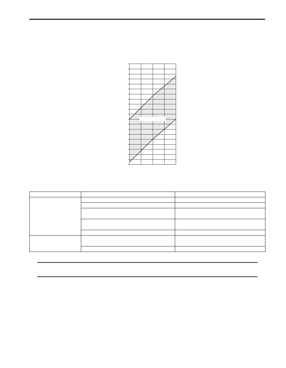
11) Check inlet port temperature-to-outlet port temperature relationship using graph.
For example, if A/C evaporator inlet port temperature is 30
°C (86 °F) and center ventilation louver temperature is
13
°C (55.4 °F), their crossing point is within acceptable range as shown in the graph in this case, cooling
performance is satisfactory and proper.
12) If crossing point is out of acceptable range, diagnose trouble referring to the following table.
Thermometer at center duct
NOTE
If ambient temperature is within 30
°C (86 °F), it is possible to diagnose A/C system in detail referring
to the following table.
T
e
mp
. at Air Outlet of Center
V
e
ntilation Louv
er
8
9
10
11
12
13
14
15
16
17
18
19
20
21
22
23
24
25
26
27
46.4
48.2
7
44.6
50.0
51.8
53.6
55.4
57.2
59.0
60.8
62.6
64.4
66.2
68.0
69.8
71.6
73.4
75.2
77.0
78.8
80.6
25
30
35
77
86
95
F C
C
F
“E”
“F”
Temp. near Air Inlet of HVAC unit
30
70
%
Humidit
y
Acceptable range
I6JB01720006-01
Condition
Possible Cause
Correction
Crossing point is higher
than acceptable range
(“E” area)
Insufficient or excessive charge of refrigerant Check refrigerant pressure.
Dirty or bent A/C evaporator fins
Clean or repair.
Air leakage from cooling (heater) unit or air
duct
Repair or replace.
Malfunctioning, switch over function of
damper in cooling (heater) unit
Repair or replace.
Compressor malfunction
Check compressor.
Crossing point is lower
than acceptable range
(“F” area)
Insufficient air volume from center duct
(Heater blower malfunction)
Check blower motor and fan.
Compressor malfunction
Check compressor.
Нет комментариевНе стесняйтесь поделиться с нами вашим ценным мнением.
Текст