Suzuki Grand Vitara JB627. Manual — part 274
7B-12 Air Conditioning System:
Customer Complaint Analysis
Record details of the problem (failure, complaint) and how it occurred as described by the customer.
For this purpose, use of such a questionnaire form as shown in the figure will facilitate collecting information to the
point required for proper analysis and diagnosis.
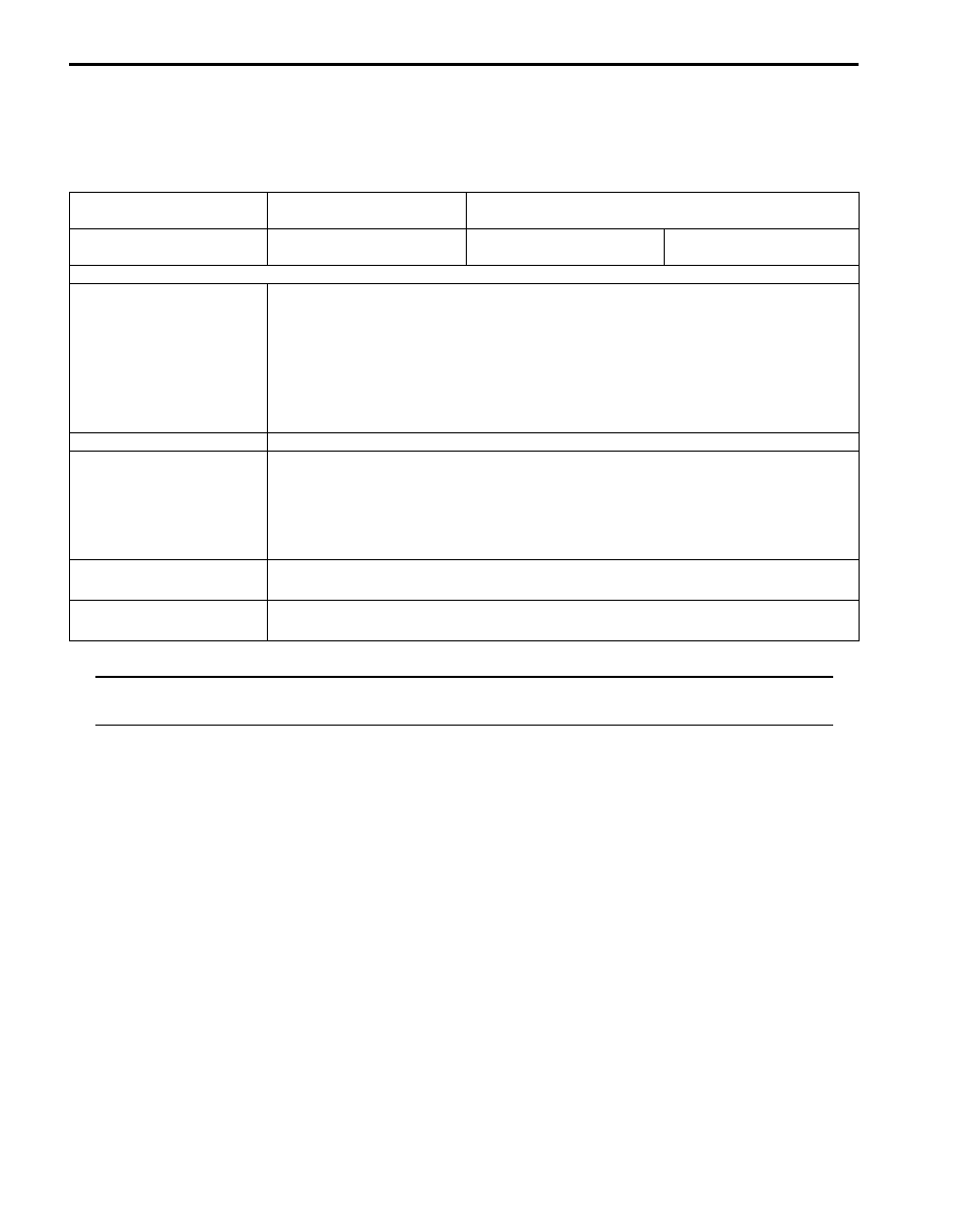
Customer questionnaire (example)
NOTE
The form is a standard sample. It should be modified according to conditions characteristic of each
market.
Visual Inspection
As a preliminary step, be sure to perform visual check of the items that support proper function of the air conditioning
system referring to “Visual Inspection”.
DTC Check
Refer to “DTC Check” for checking procedure.
Troubleshooting for DTC
Based on the DTC indicated in Step 4 and referring to applicable DTC flow, locate the cause of the trouble, namely in
a sensor, actuator, wire harness, connector, HVAC control module or other part and repair or replace faulty parts.
Check for Intermittent Problem
Check parts where an intermittent trouble is easy to occur (e.g., wire harness, connector, etc.), referring to
“Intermittent and Poor Connection Inspection in Section 00”.
Air Conditioning System Symptom Diagnosis
Check the parts or system suspected as a possible cause referring to “A/C System Symptom Diagnosis”.
Final Confirmation Test
Confirm that the problem symptom has gone and the air conditioning system is free from any abnormal conditions. If
what has been repaired is related to the malfunction DTC, check DTC once and confirm that no DTC is indicated.
Customer’s Name:
Model:
VIN:
Date of Issue:
Date Reg.
Date of Problem:
Mileage:
Problem Symptoms
• “FRE” indicator light abnormal: fails to turn ON / fails to go OFF / flashes
• Abnormal noise while “A/C” switch is turned ON: from compressor, from radiator fan
motor, other_______________
• Cool air does not come out:
• Radiator fan motor does not work:
• A/C compressor does not work:
• Blower fan motor does not work:
Frequency of Occurrence
• Continuous / Intermittent (_____ times a day, a month) / other_______________
Conditions for Occurrence of
Problem
• Vehicle at stop & A/C compressor is working:
• For some time after A/C switch is ON:
• When outside air temperature is high:
• When outside air temperature is low:
• All the time:
Environmental Condition
• Weather: fair / cloudy / rain / snow / other_______________
• Temperature: _____
°F (_____ °C)
DTC
• First check: Normal code / malfunction code (__________)
• Second check: Normal code / malfunction code (__________)
Air Conditioning System: 7B-13
DTC Check
S6JB0B7204002
NOTE
To know how to use SUZUKI scan tool in
detail, refer to its operator’s manual.
Using SUZUKI Scan Tool
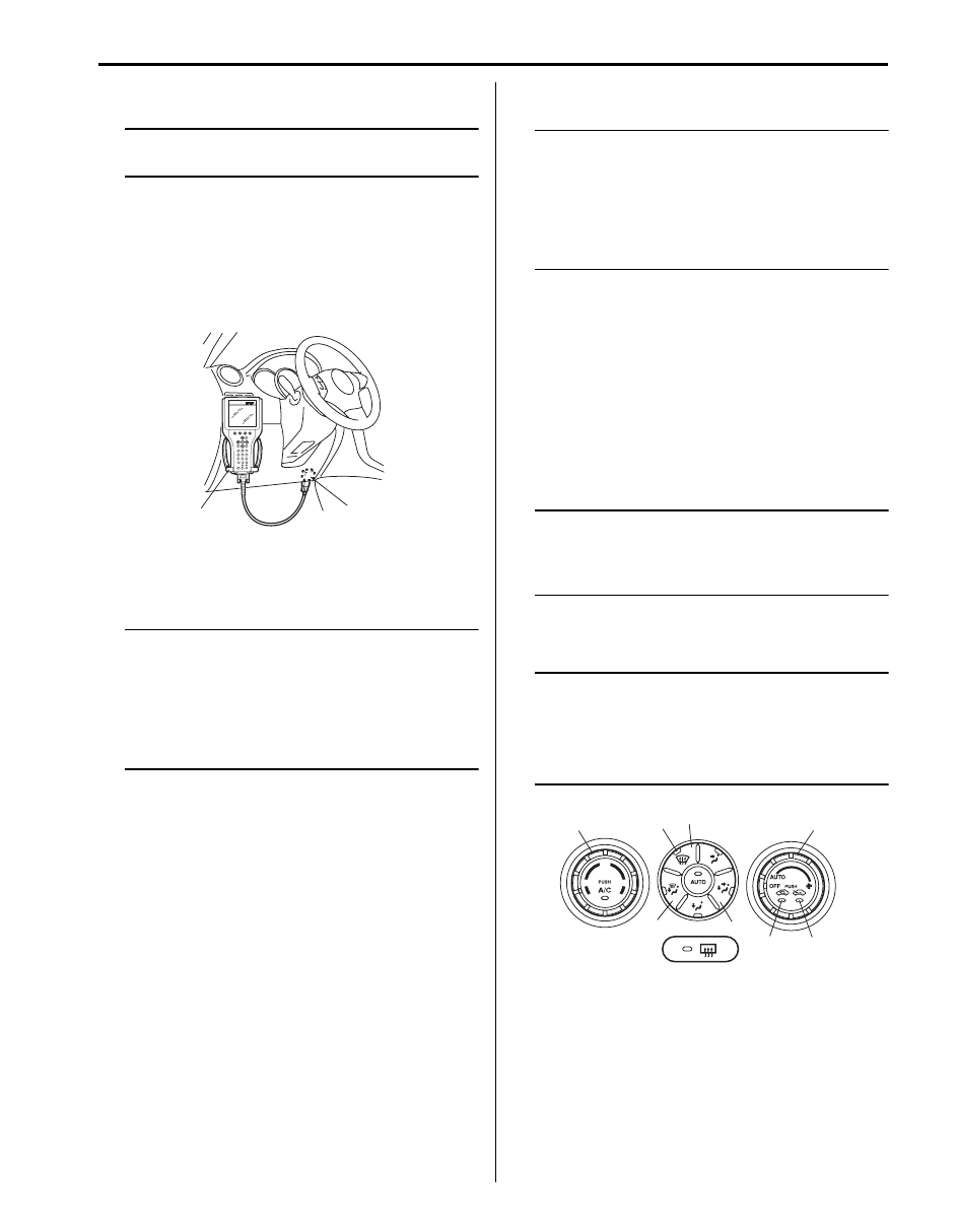
1) Turn ignition switch to OFF position.
2) Connect SUZUKI scan tool to data link connector
(DLC) (1) located on underside of instrument panel.
Special tool
(A): SUZUKI scan tool
3) Apply light to sunload sensor vertically, holding
incandescent light of approximately 100 W about
100 mm (3.94 in.) away from sunload sensor.
NOTE
If B1504 is detected when vehicle is not
exposed to light (indoor, etc.), check again
for DTC with light from incandescent light
applied to sunload sensor, referring to
“Sunload Sensor Inspection”. If B1504 is not
detected in this check, sunload sensor is in
good condition.
4) Turn ignition switch to ON position.
5) Read DTC according to instructions displayed on
SUZUKI scan tool and print it or write it down. Refer
to SUZUKI scan tool operator’s manual for further
details.
If communication between scan tool and ECM
(PCM) is not possible, check if scan tool is
communicable by connecting it to ECM (PCM) in
another vehicle. If communication is possible in this
case, scan tool is good condition. Then check data
link connector and serial data line (circuit) in the
vehicle with which communication was not possible.
6) After completing the check, turn ignition switch OFF
position and disconnect SUZUKI scan tool from data
link connector (DLC).
Not Using SUZUKI Scan Tool
NOTE
If B1504 is detected when vehicle is not
exposed to light (indoor, etc.), check again
for DTC with light from incandescent light
applied to sunload sensor, referring to
“Sunload Sensor Inspection”. If B1504 is not
detected in this check, sunload sensor is in
good condition.
1) Apply light to sunload sensor vertically, holding
incandescent light of approximately 100 W about
100 mm (3.94 in.) away from sunload sensor.
2) Set the following selectors to specified positions
respectively with turn ignition switch OFF.
• Temperature selector (1): max cool position
• Blower speed selector (2): “OFF” position
3) While pressing “B/L” (BI-LEVEL) switch (3) and “D/F”
(DEF/FOOT) switch (4) simultaneously turn ignition
switch to ON position.
NOTE
For 15 seconds after ignition switch is turned
on, both “REC” indicator light and “FRE”
indicator light light for in-system trouble
check.
4) Read DTC from flashing pattern of “FRE” indicator
(5) and “REC” indicator (6) referring to “DTC Table”.
NOTE
• Pressing “DEF” switch (7) alternates
display of current DTC and history DTC.
• “DEF” indicator light (8) remains off when
display is in current DTC mode and it lights
up when display is in history DTC mode.
(A)
1
I5JB0A720014-01
1
2
8
7
4
6
5
3
I5JB0A720015-04
7B-14 Air Conditioning System:
5) After completing above check, turn ignition switch to
“OFF” position.
NOTE
HVAC control module returns to a original
state at the following conditions.
• Ignition switch turned to “OFF” position
• Temperature selector is operated
• Blower speed selector is operated
• 5 minutes have passed since HVAC control
unit started DTC display
DTC Clearance
S6JB0B7204003
Using SUZUKI Scan Tool
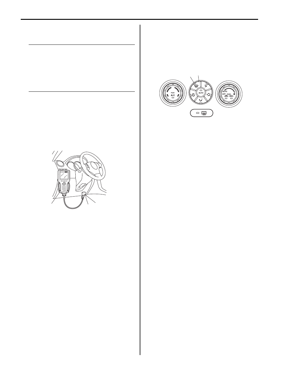
1) Turn ignition switch to OFF position.
2) Connect SUZUKI scan tool to data link connector
(DLC) (1).
Special tool
(A): SUZUKI scan tool
3) Turn ignition switch to ON position.
4) Erase DTC according to instructions displayed on
SUZUKI scan tool. Refer to SUZUKI scan tool
operator’s manual for further details.
5) After completing the clearance, turn ignition switch to
OFF position and disconnect SUZUKI scan tool from
DLC.
6) Perform “DTC Check” and confirm if normal DTC
(NO CODES) is displayed.
Not Using SUZUKI Scan Tool
1) Display history DTC by HVAC control module
referring to “Not Using SUZUKI Scan Tool” under
“DTC Check”.
2) Confirm display DTC and light “DEF” indicator light
(1).
3) Push “DEF” switch (2) at 5 seconds or more.
4) After completing the clearance, turn ignition switch
OFF position.
5) Perform “DTC Check”, and confirm if normal DTC is
displayed and if any other DTC is detected.
(A)
1
I5JB0A720014-01
1
2
I5JB0A720016-03
Air Conditioning System: 7B-15
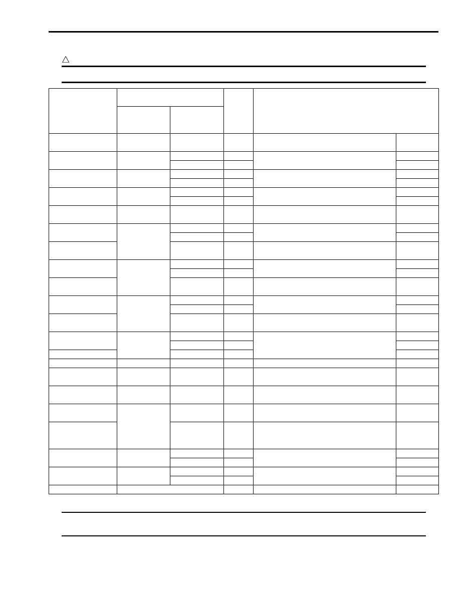
DTC Table
S6JB0B7204004
CAUTION
!
Be sure to perform “Air Conditioning System Check” before starting diagnosis.
NOTE
When no abnormality is detected, “FRE” indicator light and “REC” indicator light repeat cycle of ON
for 2 seconds and OFF for 1 second.
DTC No.
(displayed on
SUZUKI scan tool)
DTC (indicated on HVAC
control module)
Priority
of
display
Diagnosis
Indicated by
“REC”
indicator light
Indicated by
“FRE”
indicator light
B1562
1
4
1
Outside air temperature sensor and/or its
circuit malfunction
Data error
B1502
2
1
2
Inside air temperature sensor and/or its
circuit malfunction
Open
2
3
Short
B1503
3
1
4
Evaporator temperature sensor and/or its
circuit malfunction
Open
2
5
Short
B1504
4
1
29
Sunload sensor and/or its circuit
malfunction
Open
2
6
Short
B1561
5
4
7
Engine coolant temperature sensor and/or
its circuit malfunction
Data error
B1511
6
1
8
Temperature control actuator (position
sensor) and/or its circuit malfunction
Open
2
9
Short
B1513
3
10
Temperature control actuator and/or its
circuit malfunction
Lock detect
B1512
7
1
11
Air flow control actuator (position sensor)
and/or its circuit malfunction
Open
2
12
Short
B1514
3
13
Air flow control actuator and/or its circuit
malfunction
Lock detect
B1530
8
1
14
Air intake control actuator (position
sensor) and/or its circuit malfunction
Open
2
15
Short
B1531
3
16
Air intake control actuator and/or its circuit
malfunction
Lock detect
B1551
9
1
17
Serial communication circuit malfunction
Open
2
18
Short
B1552
4
19
Data error
B1553
10
4
20
CAN communication circuit malfunction
Data error
B1557
11
4
21
Wheel speed sensor and/or its circuit
malfunction
Data error
B1556
12
4
22
Camshaft position (CMP) sensor and/or its
circuit malfunction
Data error
B1563
13
4
23
A/C refrigerant pressure sensor and/or its
circuit malfunction
Data error
B1546
5
24
A/C refrigerant pressure malfunction
Refrigerant
pressure
malfunction
B1520
15
1
25
Temperature selector malfunction
Open
2
26
Short
B1521
16
1
27
Blower speed selector malfunction
Open
2
28
Short
—
See NOTE below
—
Normal
—
Нет комментариевНе стесняйтесь поделиться с нами вашим ценным мнением.
Текст