Suzuki Grand Vitara JB627. Manual — part 196
4F-23 Electronic Stability Program:
DTC C1015 / C1017 / C1023: Longitudinal G Sensor / Lateral G Sensor / Yaw Rate Sensor in Yaw Rate
/ G Sensor Assembly Failure
S6JB0B4604025
DTC Detecting Condition and Trouble Area
6
1) Check if communication is possible by trying
communication with other controller (ECM, TCM, BCM,
4WD control module or SDM).
Is it possible to communicate with other controller?
Go to Step 7.
Repair open in common
section of serial data
circuit (“PPL/WHT” wire
circuit) used by all
controllers or short to
ground or power circuit
which has occurred
somewhere in serial
data circuit (“PPL/WHT”
wire circuit).
7
1) Turn ignition switch to ON position.
2) Measure voltage between terminal B of data link
connector and vehicle body ground.
Is voltage 10 – 12 V?
Go to step 8.
Terminal B circuit open
or shorted to ground.
8
1) Turn ignition switch to OFF position.
2) Measure resistance between the following terminals;
• Terminal G of data link connector and vehicle body
ground.
• Terminal G1 of data link connector and vehicle body
ground.
Is each resistance 1
Ω
or less?
Go to step 9.
Terminal G and/or G1
circuit open or high
resistance.
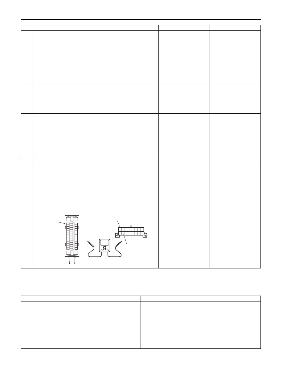
9
1) Turn ignition switch to OFF position.
2) Check proper connection at “E53-33” (“PPL/WHT” wire)
terminal for serial data circuit.
3) If OK, then check resistance between “E53-33” (“PPL/
WHT” wire) terminal and “PPL/WHT” wire terminal (2) for
serial data circuit in DLC (1).
Is resistance 1
Ω
or less?
Substitute a known-
good ESP
® hydraulic
unit / control module
and recheck.
Repair high resistance
or open in “PPL/WHT”
wire circuit for anti lock
brake system.
Step
Action
Yes
No
“E53-33”
2
1
I6JB01460015-01
DTC Detecting Condition
Trouble Area
C1015:
Longitudinal G sensor signal is out of specified range.
(4WD model)
C1017:
Lateral G sensor signal is out of specified range.
C1023:
• Yaw rate sensor signal is out of range.
• Vehicle behavior and yaw rate signal is disagreed.
• Yaw rate / G sensor assembly
• ESP
® control module
Electronic Stability Program: 4F-24
DTC Troubleshooting
DTC C1016: Brake Light Switch Circuit Failure
S6JB0B4604026
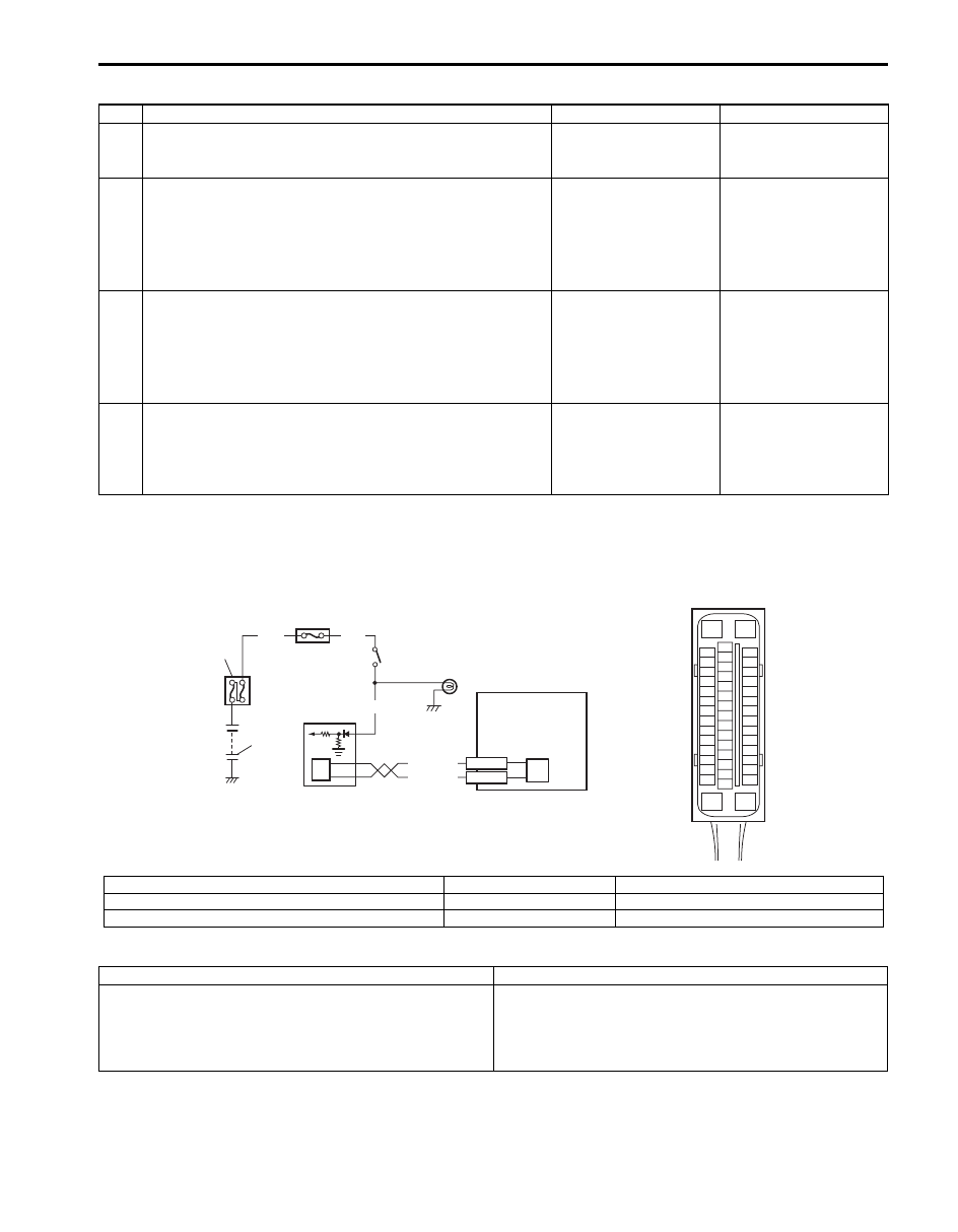
Wiring Diagram
DTC Detecting Condition and Trouble Area
Step
Action
Yes
No
1
Was “Electronic Stability Program Check” performed?
Go to Step 2.
Go to “Electronic
Stability Program
Check”.
2
DTC check for ESP
®
1) Connect scan tool to DLC with ignition switch turned
OFF.
2) Turn ignition switch ON and check DTC for ESP
®.
Are DTC C1034 and/or C1073 detected?
Go to applicable DTC
diagnosis flow for
troubleshooting.
Go to Step 3.
3
Check sensor calibration
1) Calibrate yaw rate / G sensor assembly referring to
2) Clear all DTCs and check DTC for ESP
®.
Are DTC C1015, C1017 and/or C1023 still detected?
Go to Step 4.
Yaw rate / G sensor
assembly calibration is
incompleted.
4
Check yaw rate / G sensor assembly
1) Check yaw rate / G sensor assembly referring to “Yaw
Rate / G Sensor Assembly On-Vehicle Inspection”.
Is it good condition?
Substitute a known-
good ESP
® hydraulic
unit / control module
assembly and check
DTC.
Replace yaw rate / G
sensor assembly.
3
2
1
[A]
GRN
WHT
E53-42
E53-46
6
7
E53
16
1
15
2
3
4
5
6
7
8
9
10
11
12
13
14
17
18
19
20
21
22
23
24
25
26
27
28
29
30
31
32
33
34
35
36
37
38
39
40
41
42
43
44
45
46
47
WHT/RED
WHT/BLU
GRN/WHT
4
5
7
8
I6JB01460016-01
[A]: ESP
® control module connector (viewed from terminal side)
3. Junction block assembly
6. ECM
1. Battery
4. Brake light switch
7. CAN driver
2. Main fuse box
5. Brake light
8. ESP
® hydraulic unit control module assembly
DTC Detecting Condition
Trouble Area
Vehicle behavior and brake light switch signal is disagreed
for specified time.
• Brake light switch circuit
• Brake light switch
• ECM
• ESP
® control module
4F-25 Electronic Stability Program:
DTC Troubleshooting
DTC C1018: Brake Fluid Level Switch Failure
S6JB0B4604027
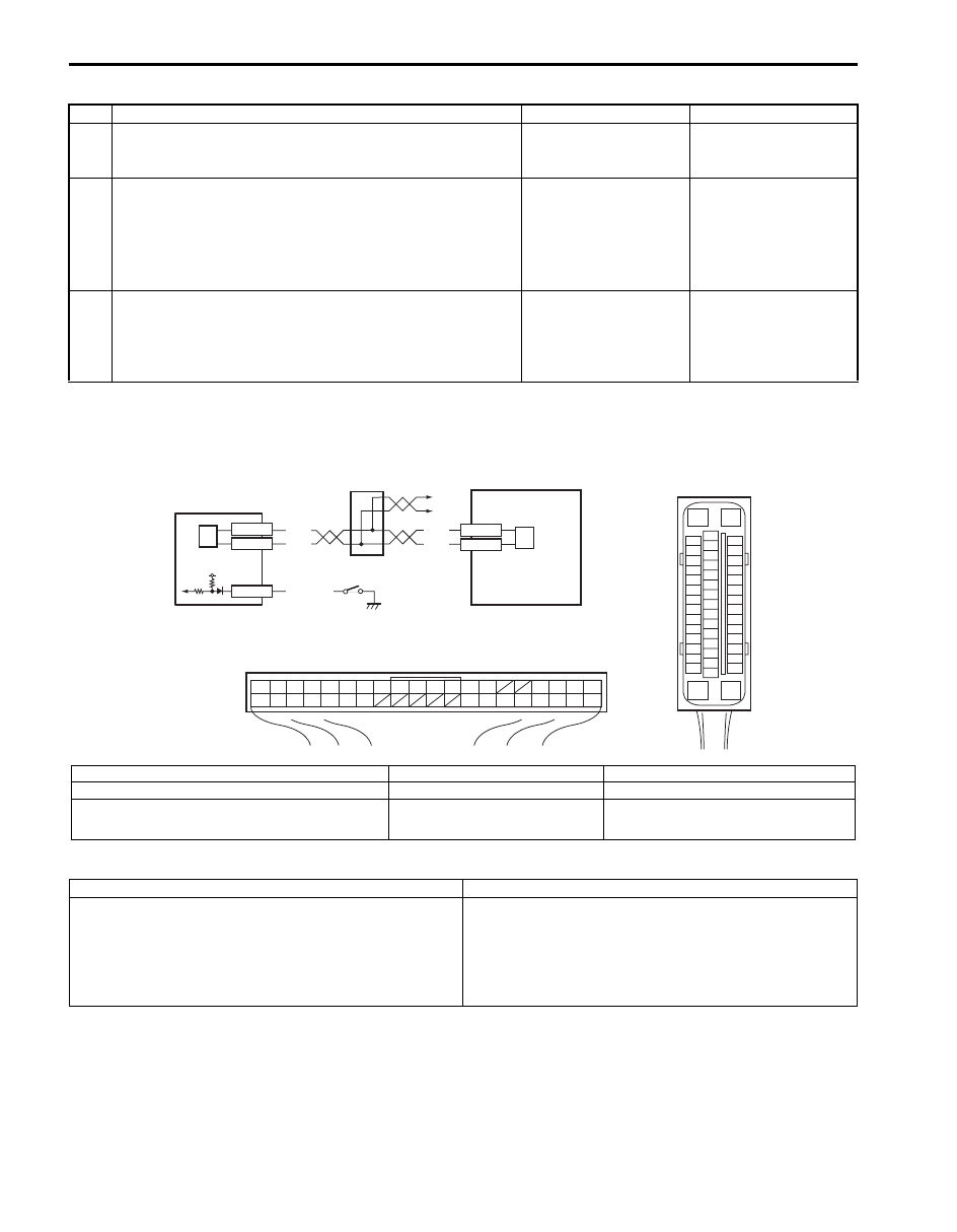
Wiring Diagram
DTC Detecting Condition and Trouble Area
Step
Action
Yes
No
1
Was “Electronic Stability Program Check” performed?
Go to Step 2.
Go to “Electronic
Stability Program
Check”.
2
DTC check for ESP
®
1) Connect scan tool to DLC with ignition switch turned
OFF.
2) Turn ignition switch ON and check DTC for ESP
®.
Is DTC U1100 detected?
Go to “DTC U1100: Lost
Communication with
ECM (Reception Error)”
for troubleshooting.
Go to Step 3.
3
DTC check for ECM
1) Check DTC for ECM.
Is there any DTC(s) for ECM?
Go to applicable DTC
diagnosis flow for
troubleshooting.
Substitute a known-
good ESP
® hydraulic
unit / control module
assembly and check
DTC.
[A]
E53
16
1
15
2
3
4
5
6
7
8
9
10
11
12
13
14
17
18
19
20
21
22
23
24
25
26
27
28
29
30
31
32
33
34
35
36
37
38
39
40
41
42
43
44
45
46
47
RED/BLK
E53-13
E53-44
RED
WHT
RED
WHT
12V
1
2
3
4
5
6
2
G31-1
G31-3
G31-7
G31
1
2
3
4
7
8
9
10
11
14
15
16
36
34
35
24 23
21
22
28 27
25
26
37
39 38
40
18 17
13 12
19
20
[B]
I6JB01460017-02
[A]: ESP
® control module connector (viewed from terminal side)
2. CAN driver
5. Brake fluid level switch
[B]: BCM connector (viewed from harness side)
3. Junction connector
6. ESP
® hydraulic unit control module assembly
1. BCM
4. To TCM, 4WD control module, keyless
start control module, combination
meter and steering angle sensor
DTC Detecting Condition
Trouble Area
• Brake fluid level is too low.
• Input voltage of brake fluid level switch to BCM is low.
• Brake fluid level
• Brake fluid level switch circuit
• Brake fluid level switch
• BCM
• ESP
® control module

Electronic Stability Program: 4F-26
DTC Troubleshooting
DTC 1020: Master Cylinder Pressure Sensor Power Supply Failure
S6JB0B4604028
DTC Detecting Condition and Trouble Area
DTC Troubleshooting
1) Turn ignition switch to OFF position.
2) Check for proper connection from harness to ESP
® control module.
3) If OK, substitute an ESP
® hydraulic unit / control module assembly with correct part number.
4) Recheck system.
Step
Action
Yes
No
1
Was “Electronic Stability Program Check” performed?
Go to Step 2.
Go to “Electronic
Stability Program
Check”.
2
Check brake fluid level
1) Check brake fluid level in reservoir.
Is brake fluid level upper than the minimum level?
Go to Step 3.
Replenish brake fluid to
reservoir.
3
DTC check for ESP
®
1) Connect scan tool to DLC with ignition switch turned
OFF.
2) Turn ignition switch ON and check DTC for ESP
®.
Is DTC U1140 detected?
Go to “DTC U1140: Lost
Communication with
BCM (Reception Error)”.
Go to Step 3.
4
Check brake fluid level switch
1) Turn ignition switch to OFF position.
2) Disconnect brake fluid level switch connector.
3) Check for proper connection at each terminal of brake
fluid level switch connector.
4) If OK, then check brake fluid level switch referring to
“Brake Fluid Level Switch Inspection in Section 9C”.
Is check result OK?
Go to Step 5.
Replace brake fluid
level switch.
5
Check brake fluid level switch circuit
1) Disconnect BCM connector.
2) Check for proper connection to BCM connector at “G31-
7” terminal.
3) If OK, then check resistance between “G31-7” terminal
and vehicle body ground.
Is resistance infinity?
Go to Step 6.
“BLKL/RED” wire circuit
is shorted to ground.
6
Check BCM
1) Connect brake fluid level switch connector and BCM
connector.
2) Check DTC for BCM.
Is there any DTC(s) in BCM?
Go to applicable DTC
diagnosis flow for
troubleshooting.
Substitute a known-
good ESP
® hydraulic
unit / control module
assembly and check
DTC.
DTC Detecting Condition
Trouble Area
Power supply voltage to master cylinder pressure sensor
in ESP
® hydraulic unit / control module assembly is too
low.
• ESP
® control module
Нет комментариевНе стесняйтесь поделиться с нами вашим ценным мнением.
Текст