Suzuki Grand Vitara JB627. Manual — part 197
4F-27 Electronic Stability Program:
DTC C1021, C1022 / C1025, C1026 / C1031, C1032 / C1035, C1036: Right-Front / Left-Front / Right-
Rear / Left-Rear Wheel Speed Sensor Circuit or Encoder Failure
S6JB0B4604014
DTC C1024: Steering Angle Sensor Circuit Failure
S6JB0B4604029
DTC Detecting Condition and Trouble Area
DTC Troubleshooting
DTC C1027: ESP
® OFF Switch Circuit Failure
S6JB0B4604030
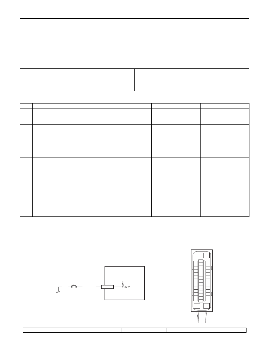
Wiring Diagram
DTC Detecting Condition
Trouble Area
• Steering angle sensor internal defect is detected by
CPU in steering angle sensor.
• Steering angle sensor signal is out of specified range.
• Steering angle sensor
• ESP
® control module
Step
Action
Yes
No
1
Was “Electronic Stability Program Check” performed?
Go to Step 2.
Go to “Electronic
Stability Program
Check”.
2
DTC check for ESP
®
1) Connect scan tool to DLC with ignition switch turned
OFF.
2) Turn ignition switch ON and check DTC for ESP
®.
Are DTC C1037 and/or U1126 detected?
Go to applicable DTC
diagnosis flow for
troubleshooting.
Go to Step 3.
3
Check sensor calibration
1) Calibrate steering angle sensor referring to “Sensor
2) Clear all DTC(s) and check DTC for ESP
®.
Is DTC C1024 still detected?
Go to Step 4.
Steering angle sensor
calibration was
incompleted.
4
Check steering angle sensor
1) Check steering angle sensor referring to “Steering Angle
Sensor On-Vehicle Inspection”.
Is it good condition?
Substitute a known-
good ESP
® hydraulic
unit / control module
assembly and check
DTC.
Replace steering angle
sensor.
[A]
E53
16
1
15
2
3
4
5
6
7
8
9
10
11
12
13
14
17
18
19
20
21
22
23
24
25
26
27
28
29
30
31
32
33
34
35
36
37
38
39
40
41
42
43
44
45
46
47
BLU/WHT
BLK
12V
E53-7
1
2
I6JB01460018-01
[A]: ESP
® control module connector (viewed from terminal side)
1. ESP
® OFF Switch
2. ESP
® hydraulic unit control module assembly

Electronic Stability Program: 4F-28
DTC Detecting Condition and Trouble Area
DTC Troubleshooting
DTC C1028: Master Cylinder Pressure Sensor Circuit Failure
S6JB0B4604031
DTC Detecting Condition and Trouble Area
DTC Troubleshooting
DTC Detecting Condition
Trouble Area
Mechanical switch failure, failure in switch wiring is
shorted to ground.
• ESP
® OFF switch
• ESP
® OFF switch circuit
• ESP
® control module
Step
Action
Yes
No
1
Was “Electronic Stability Program Check” performed?
Go to Step 2.
Go to “Electronic
Stability Program
Check”.
2
Check ESP
® OFF switch condition
Is ESP
®
OFF switch is OFF condition?
Go to Step 3.
ESP
® OFF switch
turned OFF condition
and recheck.
3
Check ESP
® OFF switch
1) Turn ignition switch to OFF position.
2) Remove ESP
® OFF switch referring to “ESP® OFF
Switch Removal and Installation”.
3) Check for proper connection at each terminal of ESP
®
OFF switch.
4) If OK, then check ESP
® OFF switch referring to “ESP®
Is it good condition?
Go to Step 4.
Replace ESP
® OFF
switch.
4
Check ESP
® OFF switch circuit
1) Disconnect ESP
® control module connector.
2) Check for proper connection to ESP
® control module
connector at “E53-7” terminal.
3) If OK, then check resistance between “E53-7” terminal
and vehicle body ground.
Is resistance infinity?
Substitute a known-
good ESP
® hydraulic
unit / control module
assembly and check
DTC.
“BLU/WHT” wire circuit
is shorted to ground.
DTC Detecting Condition
Trouble Area
Input signal voltage from master cylinder pressure sensor
in ESP
® control module is too high or low.
• Leakage or air in the hydraulic brake system
• Clearance between brake pad and disc too high
Step
Action
Yes
No
1
Was “Electronic Stability Program Check” performed?
Go to Step 2.
Go to “Electronic
Stability Program
Check”.
2
Check brake system
1) Check brake system as follows.
• Leakage or air in the hydraulic brake system
• Clearance between brake pad and disc too high
Are they in good condition?
Go to Step 3.
Repair, replace or
adjust.
3
Check sensor calibration
1) Calibrate master cylinder pressure sensor referring to
2) Clear all DTC(s) and recheck DTC.
Is DTC C1028 still detected?
Substitute a known-
good ESP
® hydraulic
unit / control module
assembly and check
DTC.
Master cylinder
pressure sensor
calibration was
incompleted.
4F-29 Electronic Stability Program:
DTC C1034: Yaw Rate / G Sensor Assembly Power Supply Failure
S6JB0B4604032
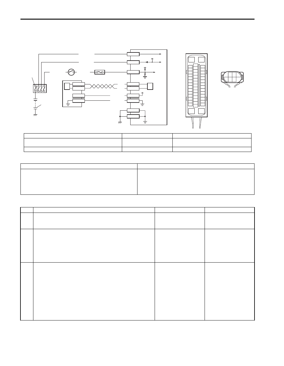
Wiring Diagram
DTC Detecting Condition and Trouble Area
DTC Troubleshooting
[A]
E53
16
1
15
2
3
4
5
6
7
8
9
10
11
12
13
14
17
18
19
20
21
22
23
24
25
26
27
28
29
30
31
32
33
34
35
36
37
38
39
40
41
42
43
44
45
46
47
1
E53-16
E53-47
12V
12V
E53-32
E53-1
E53-35
BLK/YEL
WHT/GRN
WHT/RED
WHT/BLU
E53-29
E53-25
E53-37
E53-31
L39-3
L39-5
BLK
WHT
L39-2
L39-1
12V
PNK/GRN
PNK/WHT
[B]
L39
3
5
2 1
4
6
2
3
5
6
4
7
6
I6JB01460019-03
[A]: ESP
® control module connector (viewed from terminal side)
2. Main fuse box
5. Yaw rate / G sensor assembly
[B]: Yaw rate / G sensor assembly connector (viewed from
harness side)
3. Ignition switch
6. CAN driver
1. Battery
4. Junction block assembly
7. ESP
® hydraulic unit / control module assembly
DTC Detecting Condition
Trouble Area
• Power supply voltage of yaw rate / G sensor assembly
is too high when ignition switch OFF.
• Power supply voltage of yaw rate / G sensor assembly
is too low when ignition switch ON.
• Yaw rate / G sensor assembly power supply circuit
• ESP
® control module power supply circuit
• Yaw rate / G sensor assembly
• ESP
® control module
Step
Action
Yes
No
1
Was “Electronic Stability Program Check” performed?
Go to Step 2.
Go to “Electronic
Stability Program
Check”.
2
DTC check for ESP
®
1) Connect scan tool to DLC with ignition switch turned
OFF.
2) Turn ignition switch ON and check DTC for ESP
®.
Are DTC C1057 and/or C1073 detected?
Go to applicable DTC
diagnosis flow for
troubleshooting.
Go to Step 3.
3
Check yaw rate / G sensor assembly power supply
circuit
1) Turn ignition switch to OFF position.
2) Disconnect yaw rate / G sensor assembly connector.
3) Check for proper connection to yaw rate / G sensor
assembly connector terminals at “L39-3” and “L39-5”.
4) If OK, then measure voltage between connector terminal
“L39-3” and vehicle body ground.
Is it 0 V?
Go to Step 4.
Go to Step 5.
Electronic Stability Program: 4F-30
DTC C1037: Steering Angle Sensor Power Supply Failure
S6JB0B4604033
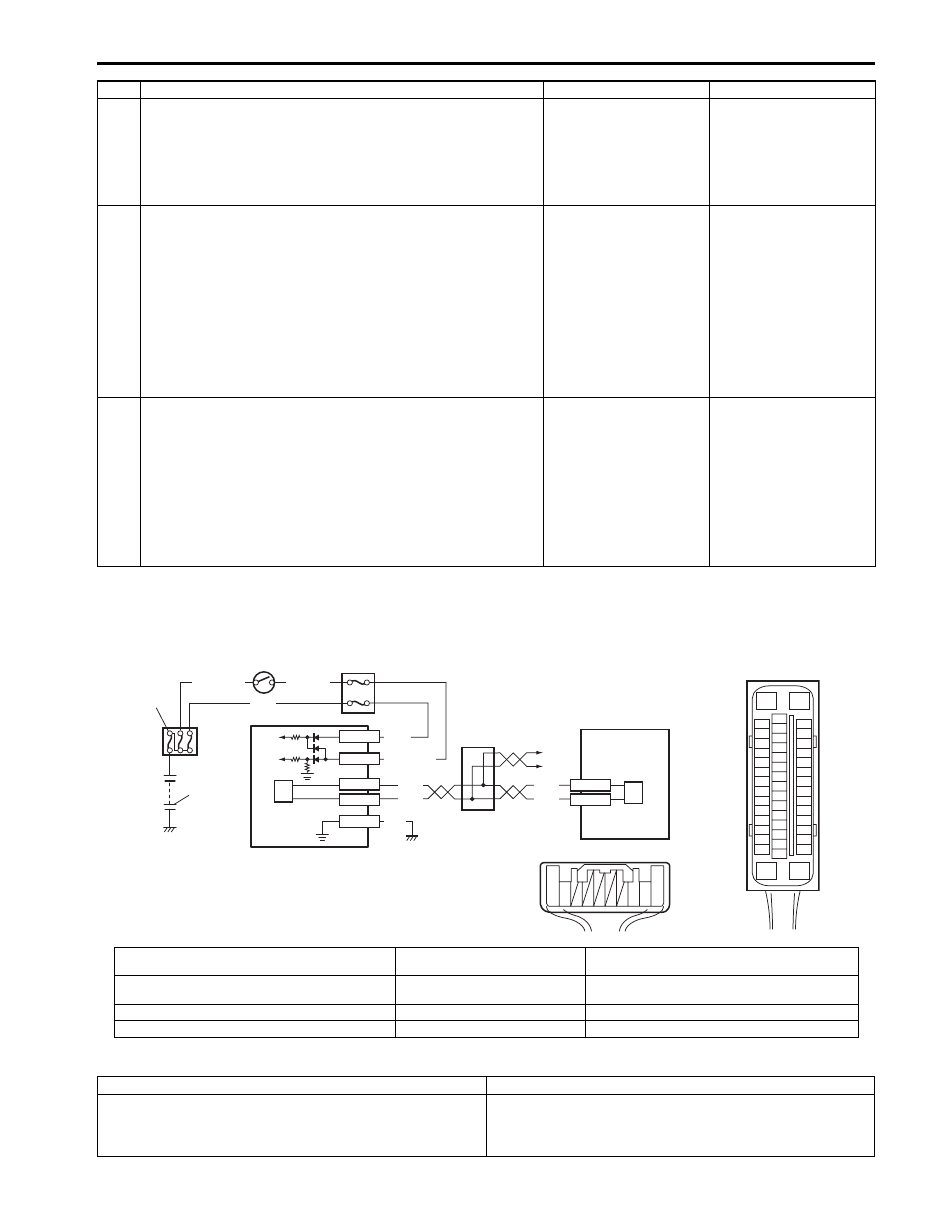
Wiring Diagram
DTC Detecting Condition and Trouble Area
4
Check yaw rate / G sensor assembly power supply
circuit
1) Measure voltage between connector terminal “L39-3”
and “L39-5” with ignition switch turned ON.
Is it 10 – 14 V?
Substitute a known-
good yaw rate / G
sensor assembly and
check DTC.
Go to Step 5.
5
Check yaw rate / G sensor assembly power supply
circuit
1) Turn ignition switch to OFF position.
2) Disconnect ESP
® control module connector.
3) Check for proper connection to ESP
® control module
connector terminals at “E53-31” and “E53-37”.
4) If OK, then measure voltage between connector terminal
“E53-37” and vehicle body ground.
Is it 0 V?
Go to Step 6.
“PNK/WHT” wire circuit
is shorted to power
circuit.
6
Check yaw rate / G sensor assembly power supply
circuit
1) Measure resistance between the following points.
• Between terminal “E53-37” of module connector and
terminal “L39-3” of sensor terminal.
• Between terminal “E53-31” of module connector and
terminal “L39-5” of sensor terminal.
Are resistance less than 2
Ω
?
Substitute a known-
good ESP
® hydraulic
unit / control module
assembly and check
DTC.
“PNK/WHT” and/or
“PNK/GRN” wire circuit
open or high resistance.
Step
Action
Yes
No
[A]
E53
16
1
15
2
3
4
5
6
7
8
9
10
11
12
13
14
17
18
19
20
21
22
23
24
25
26
27
28
29
30
31
32
33
34
35
36
37
38
39
40
41
42
43
44
45
46
47
E53-13
E53-44
RED
WHT
RED
WHT
WHT
GRN/ORN
G45-3
G45-1
BLK
G45-2
G45-10
G45-9
BLK/YEL
WHT/GRN
1
WHT
[B]
G45
10 9
3 2 1
2
3
4
5
6
7
8
9
6
I6JB01460020-02
[A]: ESP
® control module connector (viewed from
terminal side)
3. Ignition switch
7. Junction connector
[B]: Steering angle sensor connector (viewed from
harness side)
4. Junction block assembly
8. To TCM, BCM, 4WD control module, keyless start
control module and combination meter
1. Battery
5. Steering angle sensor
9. ESP
® hydraulic unit / control module assembly
2. Main fuse box
6. CAN driver
DTC Detecting Condition
Trouble Area
Power supply voltage to steering angle sensor is too low. • Steering angle sensor power supply circuit
• Steering angle sensor
• ESP
® control module
Нет комментариевНе стесняйтесь поделиться с нами вашим ценным мнением.
Текст