Suzuki Grand Vitara JB627. Manual — part 34
1A-85 Engine General Information and Diagnosis:
DTC Troubleshooting
NOTE
Before this trouble shooting is performed, read the precautions for DTC troubleshooting referring to
“Precautions for DTC Troubleshooting”.
Step
Action
Yes
No
1
Was “Engine and Emission Control System Check”
performed?
Go to Step 2.
Go to “Engine and
Emission Control
System Check”.
2
Engine coolant temperature check
1) With ignition switch OFF install scan tool.
2) With ignition switch ON, check engine coolant
temperature displayed on scan tool. (ECT 1)
3) Warm up engine to normal operating temperature.
4) Check engine coolant temperature displayed on scan
tool. (ECT 2)
Is difference between ECT 1 and ECT 2 less than 1
°
C?
Go to Step 4.
Go to Step 3.
3
Thermostat check
1) Check thermostat referring to “Thermostat Inspection in
Is thermostat in good condition?
Go to Step 4.
Replace thermostat.
4
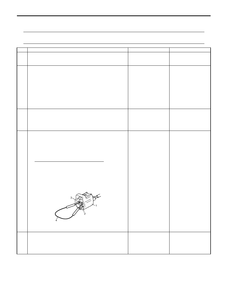
ECT sensor circuit check
1) With ignition switch OFF, install scan tool and disconnect
ECT sensor connector (1).
2) With ignition switch ON, check engine coolant
temperature displayed on scan tool.
ECT sensor temperature specifications
Signal wire terminal (2) and ground wire terminal (3)
in ECT sensor connector are shorted by service wire
(4): 205
°C
Signal wire terminal (2) and ground wire terminal (3)
in ECT sensor connector are opened: –40
°C
Is each result satisfied its specification?
Go to Step 5.
Check ECT sensor
signal and ground
circuits referring to Step
2 of “DTC P0117 /
P0118: Engine Coolant
Temperature Circuit
Low / High Input”.
5
ECT sensor performance check
1) Check ECT sensor referring to “Engine Coolant
Temperature (ECT) Sensor Inspection in Section 1C”.
Is check result as specified?
Substitute a known
good ECM and recheck.
Replace ECT sensor.
I6JB01110032-01

Engine General Information and Diagnosis: 1A-86
DTC P0117 / P0118: Engine Coolant Temperature Circuit Low / High Input
S6JB0B1104024
Wiring Diagram
Refer to “DTC P0116: Engine Coolant Temperature Circuit Range / Performance”.
DTC Detecting Condition and Trouble Area
DTC Confirmation Procedure
1) With ignition switch OFF, connect scan tool.
2) Turn ON ignition switch and clear DTC by using scan tool if any.
3) Start engine and run it for 10 sec.
4) Check DTC by using scan tool.
DTC Troubleshooting
NOTE
Before this trouble shooting is performed, read the precautions for DTC troubleshooting referring to
“Precautions for DTC Troubleshooting”.
DTC detecting condition
Trouble area
P0117: Engine Coolant Temperature Circuit Low Input
Circuit voltage of ECT sensor is less than 0.16 V for 5 seconds or longer.
(1 driving cycle detection logic)
• ECT sensor and its circuit
• ECM
P0118: Engine Coolant Temperature Circuit High Input
Circuit voltage of ECT sensor is more than 5.0 V for 5 seconds or longer.
(1 driving cycle detection logic)
Step
Action
Yes
No
1
Was “Engine and Emission Control System Check”
performed?
Go to Step 2.
Go to “Engine and
Emission Control
System Check”.
2
Wire harness check
1) Turn ignition switch OFF position.
2) Disconnect connectors from ECT sensor and ECM.
3) Check for proper terminal connection to ECT sensor and
ECM connectors.
4) If connections are OK, check that ECT sensor circuit is
as follows.
• Wiring harness resistance of each ECT sensor signal
and ground circuit is less than 3
Ω.
• Insulation resistance of ECT sensor signal circuit is
infinity between ECT sensor connector and vehicle
body ground.
• Insulation resistance of wire harness is infinity
between ECT sensor signal terminal and each other
terminal at ECT sensor connector.
• Circuit voltage of each ECT sensor signal and ground
circuit is 0 – 1 V with ignition switch turned ON.
Are they in good condition?
Go to Step 3.
Repair or replace
defective wire harness.
3
ECT sensor reference voltage check
1) Connect connectors to ECM.
2) Turn ignition switch to ON position.
3) Check that ECT sensor signal voltage is 5 V between
ECT sensor connector and vehicle body ground.
Is it in good condition?
Go to Step 4.
Substitute a known
good ECM and recheck.
1A-87 Engine General Information and Diagnosis:
DTC P0122 / P0123: Throttle Position Sensor (Main) Circuit Low / High Input
S6JB0B1104025
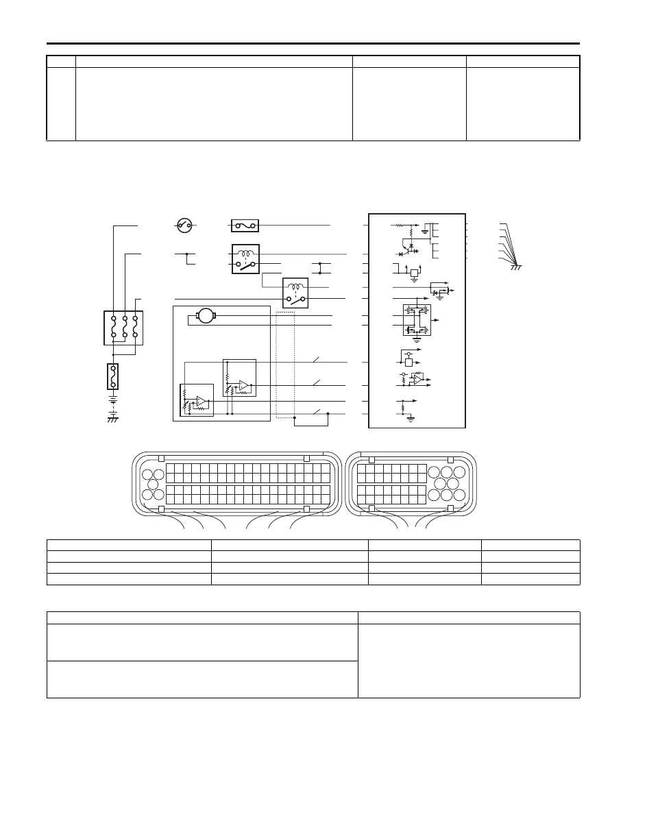
Wiring Diagram
DTC Detecting Condition and Trouble Area
DTC Confirmation Procedure
1) With ignition switch OFF, connect scan tool.
2) Turn ON ignition switch and clear DTC by using scan tool if any.
3) Start engine and run it for 10 sec.
4) Check DTC by using scan tool.
4
ECT sensor check
1) Check ECT sensor for performance referring to “Engine
Coolant Temperature (ECT) Sensor Inspection in
Section 1C”.
Is it in good condition?
Substitute a known
good ECM and recheck.
Replace ECT sensor.
Step
Action
Yes
No
BLU/BLK
BLU/BLK
BLU/BLK
BLK/RED
BLK/RED
BLK/RED
BLU
12V 5V
E23-8
E23-16
E23-2
E23-3
WHT/GRN
C37-59
C37-58
C37-39
C37-73
C37-80
BLK/YEL
BLK/ORN
BLK/ORN
BLK/YEL
BLK/YEL
1
3 2
4
5
6
7
8
9
1110
12
13
14
15
16
17
18
19
20
17
18
19
20
21
22
23
24
25
26
27
28
29
30
31
33
34
35
36
37
38
39
40
32
1
2
3
4
5
6
7
8
9
10
11
12
13
14
15
16
21
22
23
24
25
26
27
28
29
30
31
32
33
34
35
36
37
38
39
40
41
42
43
44
45
46
47
48
49
50
51
52
53
54
55
56
57
58
59
60
61
62
63
64
65
66
67
68
69
70
71
72
73
74
75
76
77
78
79
80
81
E23
C37
BLK/ORN
C37-81
BLK/YEL
BLK/WHT
BLU/ORN
GRN
BLU/YEL
BLU/RED
BLU/BLK
E23-6
E23-7
E23-5
E23-4
C37-45
C37-46
C37-65
C37-64
BLU/RED
WHT
GRN
RED
BLK
P
S
G
8
11 10 9
13
12
7
5
2
1
4
3
6
I6JB01110033-03
P: TP sensor power supply circuit
2. Throttle actuator
6. ECM
10. “FI” fuse
S: TP sensor signal circuit
3. Throttle position sensor (main)
7. Main relay
11. “IGN” fuse
G: TP sensor ground circuit
4. Throttle position sensor (sub)
8. Fuse Box No.2
12. “IG COIL” fuse
1. Electric throttle body assembly
5. Throttle actuator control relay
9. “THR MOT” fuse
13. Ignition switch
DTC detecting condition
Trouble area
P0122: Throttle Position Sensor (Main) Circuit Low Circuit
Output voltage of TP sensor (main) is less than 0.3 V.
(1 driving cycle detection logic)
• Electric throttle body assembly
• TP sensor main circuit
• ECM
P0123: Throttle Position Sensor (Main) Circuit High Circuit
Output voltage of TP sensor (main) is more than 4.5 V.
(1 driving cycle detection logic)

Engine General Information and Diagnosis: 1A-88
DTC Troubleshooting
NOTE
• Before this trouble shooting is performed, read the precautions for DTC troubleshooting referring to
“Precautions for DTC Troubleshooting”.
• When DTC P0122 and P0222 are indicated together, it is possible that TP sensor power supply
circuit is open.
• When DTC P0123 and P0223 are indicated together, it is possible that TP sensor power supply
circuit is shorted to power circuit and / or TP sensor ground circuit is open.
Step
Action
Yes
No
1
Was “Engine and Emission Control System Check”
performed?
Go to Step 2.
Go to “Engine and
Emission Control
System Check”.
2
Throttle position sensor and its circuit check
1) Connect scan tool to DLC with ignition switch turned
OFF.
2) Turn ON ignition switch, check “TP Sensor 1 Volt”
displayed on scan tool when accelerator pedal is idle
position and fully depressed.
Is displayed TP sensor value as described voltage in “Scan
Tool Data”?
Intermittent trouble.
Check for intermittent
referring to “Intermittent
and Poor Connection
Inspection in Section
00”.
Go to Step 3.
3
Wire harness check
1) Turn ignition switch OFF position.
2) Disconnect connectors from TP sensor and ECM.
3) Check for proper terminal connection to electric throttle
body assembly and ECM connectors.
4) If connections are OK, check that TP sensor (main)
circuit is as follows.
• Wiring harness resistance of each TP sensor (main)
signal, power supply and ground circuit is less than
3
Ω.
• Insulation resistance of each TP sensor (main) signal
and power supply circuit is infinity between TP sensor
connector and vehicle body ground.
• Insulation resistance of wire harness is infinity
between TP sensor (main) signal terminal and each
other terminal at TP sensor connector.
• Circuit voltage of each TP sensor (main) signal, power
supply and ground circuit is 0 – 1 V with ignition
switch turned ON.
Are they in good condition?
Go to Step 4.
Repair or replace
defective wire harness.
4
TP sensor circuit voltage check
1) Connect connector from ECM.
2) Turn ignition switch ON position.
3) Check that TP sensor circuit voltage is as follows.
• Between TP sensor power supply terminal and TP
sensor ground terminal is 5 V.
• Between TP sensor (main) signal terminal and TP
sensor ground terminal is 5 V.
Is it in good condition?
Go to Step 5.
Substitute a known
good ECM and recheck.
Нет комментариевНе стесняйтесь поделиться с нами вашим ценным мнением.
Текст