Suzuki Grand Vitara JB627. Manual — part 201

4F-43 Electronic Stability Program:
6
DTC check for ESP
®
1) Turn ignition switch to OFF position.
2) Disconnect connectors of all control modules
communicating by means of CAN.
3) Connect connectors to ESP
® control module and BCM.
4) Check DTC for ESP
®.
Is DTC U1140 detected?
Go to Step 7.
Go to Step 9.
7
DTC Check for ECM
1) Check DTC for ECM.
Is DTC U0140 detected?
Go to Step 8.
Check ESP
® control
module power and
ground circuit. If circuit
is OK, substitute a
known-good ESP
®
control module and
check DTC.
8
CAN communication circuit check
1) Turn ignition switch to OFF position
2) Disconnect connectors of ESP
® control module, BCM
and ECM communicating by means of CAN.
3) Measure resistance at following terminals.
• Between “WHT/BLU” and “WHT” wire terminals of
ESP
® control module connector
• Between “WHT/RED” and “RED” wire terminals of
ESP
® control module connector
Is resistance below 1
Ω
?
Check BCM power and
ground circuit. If circuit
is OK, substitute a
known-good BCM and
check DTC.
Substitute a known-
good ESP
® control
module and check DTC.
9
CAN communication circuit check
1) Turn ignition switch to OFF position.
Is each CAN communication circuit between disconnected
control modules (other than ESP
®
control module and BCM)
opened, shorted or high resistance?
Repair or replace the
CAN communication
line.
Go to Step 10.
10 DTC check for ESP
®
1) Connect connectors of disconnected control modules
communicating by means of CAN.
2) Disconnect each connector.
• ECM
• TCM (A/T model)
• BCM
• 4WD control module (if equipped)
• Keyless start control module (if equipped)
• Steering angle sensor
3) Check DTC for ESP
®.
Is DTC U1140 detected?
Check ESP
® control
module power and
ground circuit. If circuits
are OK, substitute a
known-good ESP
®
hydraulic unit / control
module assembly and
check DTC.
Check applicable
control module power
and ground circuit. If
circuit is OK, substitute
a known-good
applicable control
module and check DTC.
Step
Action
Yes
No

Electronic Stability Program: 4F-44
Repair Instructions
Hydraulic Unit Operation Check
S6JB0B4606001
Refer to “Hydraulic Unit Operation Check in Section 4E”.
Sensor Calibration
S6JB0B4606015
CAUTION
!
If any DTC(s) other than C1075, C1076, C1077
or C1078 are detected, sensor calibration can
not be completed. Repair the detected DTC
first.
NOTE
Steering angle sensor calibration is needed
when battery, dome fuse or the steering
angle sensor is removed.
This sensor calibration can be done with/
without SUZUKI Scan Tool.
When ESP
® control module and/or yaw rate /
G sensor assembly is removed, sensor
calibration is needed with SUZUKI Scan Tool.
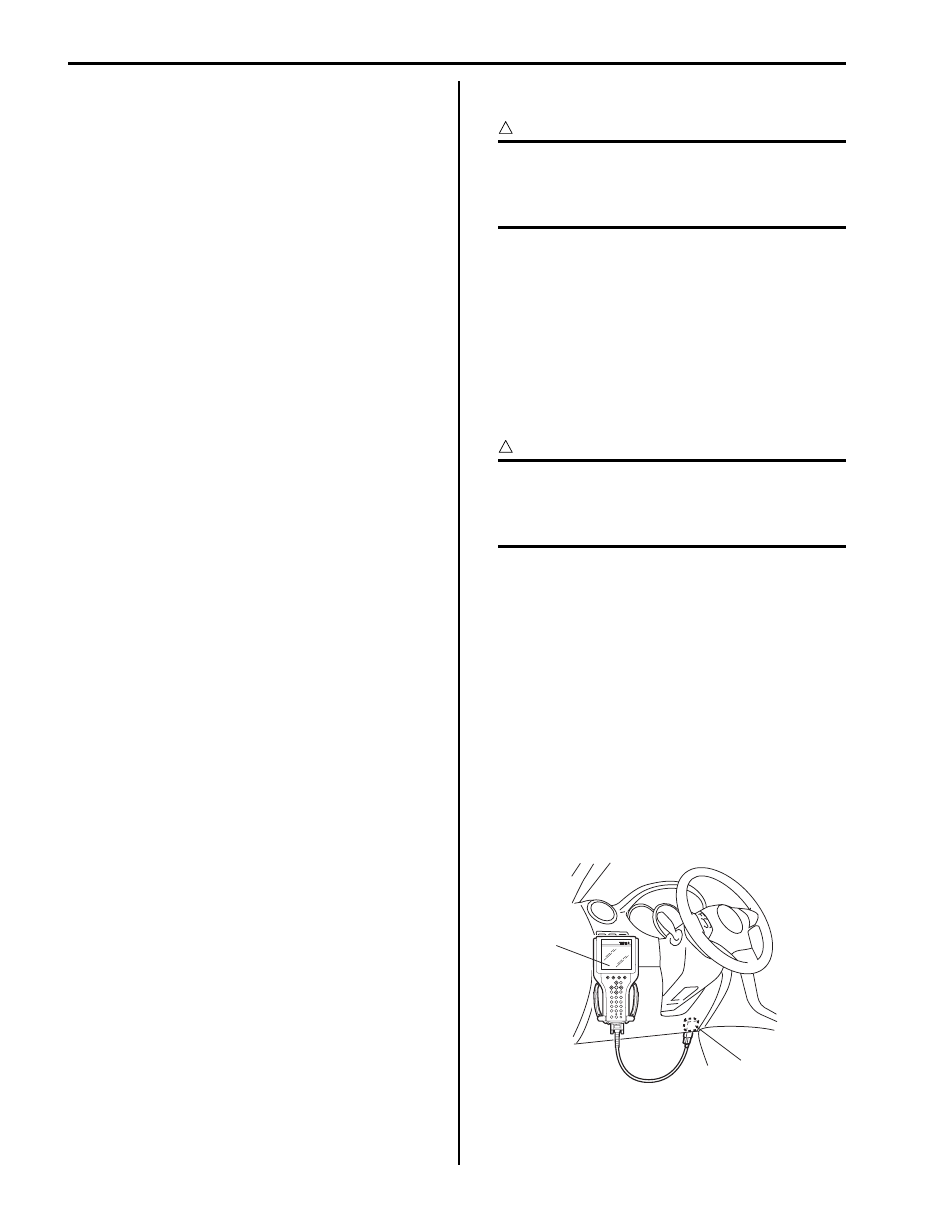
Sensor Calibration (Using SUZUKI Scan Tool)
1) Set steering wheel in straight-ahead position.
2) Connect SUZUKI scan tool to data link connector
(DLC) (1) with ignition switch OFF.
Special tool
(A): SUZUKI scan tool
3) Turn ignition switch to ON position and confirm that
only any of DTC(s) C1075, C1076, C1077 and/or
C1078 is detected. If any other DTC are detected,
repair the detected DTC.
4) Park and level the vehicle with parking brake, stop
engine with ignition switch ON, set steering in
straight and without stepping on the brake pedal.
CAUTION
!
Hold the above condition in Step 4) to
calibrate sensor correctly until sensor
calibration is completed.
5) Select menu “SENSOR CALIBRATION” under
“MISC. TEST” mode of SUZUKI scan tool and
calibrate sensor. Refer to scan tool operator's
manual for further derails.
6) After completing the calibration, turn ignition switch
to OFF position and disconnect SUZUKI scan tool
from DLC.
Steering Angle Sensor Calibration (Not Using
SUZUKI Scan Tool)
CAUTION
!
When power is not supplied to the steering
angle sensor by removing battery or fuse,
steering angle sensor should be calibrated.
1) Set steering wheel in straight-ahead position.
2) Connect battery terminals and/or fuse and start
engine.
CAUTION
!
When power is not supplied to the steering
angle sensor by removing battery or fuse,
DTC C1075 is detected and SLIP indicator
light (1) flashes.
If DTC other than C1075 is detected, SLIP
indicator light flushes and other indicator
illuminate. In that case, repair the detected
DTC first.
3) Drive vehicle straight on level ground at 15 km/h (9.5
mph) or above for few seconds without spinning
wheels. And confirm that SLIP indicator light is OFF.
(A)
1
I5JB0A450008-01
1
I6JB01460024-02
4F-45 Electronic Stability Program:
ESP
® Hydraulic Unit / Control Module
Assembly Components
S6JB0B4606002
®) hydraulic unit / control module
Assembly Components in Section 4E”.
ESP
® Hydraulic Unit / Control Module
Assembly On-Vehicle Inspection
S6JB0B4606003
®) hydraulic unit / control module
Assembly On-Vehicle Inspection in Section 4E”.
ESP
® Hydraulic Unit / Control Module
Assembly Removal and Installation
S6JB0B4606004
®) hydraulic unit / control module
Assembly Removal and Installation in Section 4E”.
Front Wheel Speed Sensor On-Vehicle
Inspection
S6JB0B4606005
Refer to “Front Wheel Speed Sensor On-Vehicle
Inspection in Section 4E”.
Front Wheel Speed Sensor Removal and
Installation
S6JB0B4606006
Refer to “Front Wheel Speed Sensor Removal and
Installation in Section 4E”.
Front Wheel Speed Sensor Inspection
S6JB0B4606007
Refer to “Front Wheel Speed Sensor Inspection in
Section 4E”.
Rear Wheel Speed Sensor On-Vehicle
Inspection
S6JB0B4606008
Refer to “Front Wheel Speed Sensor On-Vehicle
Inspection” since rear wheel speed sensor is the same
as front wheel speed sensor.
Rear Wheel Speed Sensor Removal and
Installation
S6JB0B4606009
Refer to “Rear Wheel Speed Sensor Removal and
Installation in Section 4E”.
Rear Wheel Speed Sensor Inspection
S6JB0B4606010
Refer to “Front Wheel Speed Sensor Inspection” since
rear wheel speed sensor is the same as front wheel
speed sensor.
Front Wheel Encoder On-Vehicle Inspection
S6JB0B4606011
Refer to “Front Wheel Encoder On-Vehicle Inspection in
Section 4E”.
Front Wheel Encoder Removal and Installation
S6JB0B4606012
CAUTION
!
Front wheel encoder is included in front
wheel hub assembly. If front wheel encoder
needs to replaced, replace it as a front wheel
hub assembly.
For removal and installation of front wheel hub
assembly, referring to “Front Wheel Hub Assembly
Removal and Installation in Section 2B”.
Rear Wheel Encoder On-Vehicle Inspection
S6JB0B4606013
Refer to “Rear Wheel Encoder On-Vehicle Inspection in
Section 4E”.
Rear Wheel Encoder Removal and Installation
S6JB0B4606014
CAUTION
!
Rear wheel encoder is included in rear wheel
hub assembly. If rear wheel encoder needs to
replaced, replace it as a rear wheel hub
assembly.
For removal and installation of front wheel hub
assembly, referring to “Rear Wheel Hub Assembly
Removal and Installation in Section 2C”.
Master Cylinder Pressure Sensor On-Vehicle
Inspection
S6JB0B4606016
1) Calibrate yaw rate / G sensor assembly referring to
2) Check that basic brake system other than ESP
®
refer to “Brake Diagnosis Note in Section 4A”.
3) Connect SUZUKI scan tool to data link connector
(DLC) (1) with ignition switch OFF.
Special tool
(A): SUZUKI scan tool
(A)
1
I5JB0A450008-01
Electronic Stability Program: 4F-46
4) Turn ignition switch to ON position and select menu
“DATA LIST” mode of SUZUKI scan tool. Refer to
scan tool operator's manual for further derails.
5) When brake pedal is released, check “Master Cyl
Press” under “DATA LIST” of SUZUKI scan tool.
If pressure is out of specification, replace ESP
®
hydraulic unit / control module assembly.
Master cylinder pressure specification
Brake pedal released: 0
± 0.8 MPa (0 ± 8 kg/cm
2
, 0
± 113 psi)
6) Hoist vehicle and remove right-side front wheel.
7) Connect special tool with rubber hose (1) to Front
brake caliper bleeder plug (2).
Special tool
(A): 09956–02311
8) When bleeder plug loosen and depress brake pedal
to make special tool gauge reading 10 MPa (100 kg/
cm
2
, 1422 psi), check “Master Cyl Press” under
“DATA LIST” of SUZUKI scan tool.
If pressure displayed on SUZUKI scan tool is out of
specification, replace ESP
® hydraulic unit / control
module assembly.
Master cylinder pressure specification
Brake pedal depressed 10 MPa (100 kg/cm
2
, 1422
psi): 10
± 1.2 MPa (100 ± 12 kg/cm
2
, 1422
± 170
psi)
9) After completing the check, turn ignition switch to
OFF position and disconnect SUZUKI scan tool from
DLC.
10) Tighten bleeder plug and bleed air from brake
system, referring to “Air Bleeding of Brake System in
Section 4A”.
Yaw Rate / G Sensor Assembly On-Vehicle
Inspection
S6JB0B4606017
Longitudinal G Inspection
1) Calibrate yaw rate / G sensor assembly referring to
2) Park and level the vehicle with parking brake and fix
wheels with chokes.
3) Check yaw rate / G sensor assembly installation
condition.
4) Connect SUZUKI scan tool to data link connector
(DLC) (1) with ignition switch OFF.
Special tool
(A): SUZUKI scan tool
5) Turn ignition switch to ON position and select menu
“DATA LIST” mode of SUZUKI scan tool. Refer to
scan tool operator's manual for further derails.
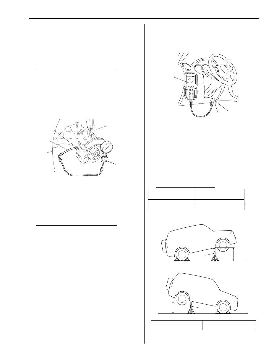
6) Check “G Sensor” under “DATA LIST” of SUZUKI
scan tool in the following vehicle conditions.
• Level condition
• Front-up condition
• Rear-up condition
If Longitudinal G condition is out of specification,
replace yaw rate / G sensor assembly.
Longitudinal G specification
2
(A)
1
I6JB01460025-01
Vehicle condition
Longitudinal G
Level condition
0
± 0.1 G
Front-up condition
0.1
± 0.1 G
Rear-up condition
–0.1
± 0.1 G
[A]: Front-up condition
“a”: Approx 400 mm (15.75 in.)
[B]: Rear-up condition
1. Safety stand
(A)
1
I5JB0A450008-01
[A]
[B]
“a”
“a”
1
1
I6JB01460026-02
Нет комментариевНе стесняйтесь поделиться с нами вашим ценным мнением.
Текст