Suzuki Grand Vitara JB627. Manual — part 202
4F-47 Electronic Stability Program:
Lateral G Inspection
1) Calibrate yaw rate / G sensor assembly referring to
2) Park and level the vehicle with parking brake and fix
wheels with chokes.
3) Check yaw rate / G sensor assembly installation
condition.
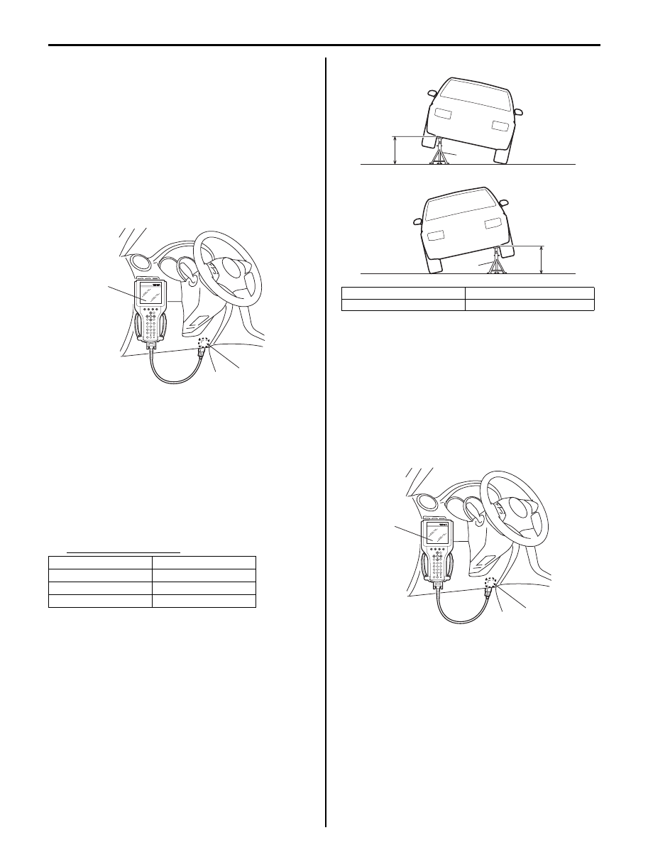
4) Connect SUZUKI scan tool to data link connector
(DLC) (1) with ignition switch OFF.
Special tool
(A): SUZUKI scan tool
5) Turn ignition switch to ON position and select menu
“DATA LIST” mode of SUZUKI scan tool. Refer to
scan tool operator's manual for further derails.
6) Check “G Sensor (lateral)” under “DATA LIST” of
SUZUKI scan tool in the following vehicle conditions.
• Level condition
• Right-up condition
• Left-up condition
If Lateral G condition is out of specification, replace
yaw rate / G sensor assembly.
Lateral G specification
Yaw Rate Inspection
1) Calibrate yaw rate / G sensor assembly referring to
2) Check yaw rate / G sensor assembly installation
condition.
3) Connect SUZUKI scan tool to data link connector
(DLC) (1) with ignition switch OFF.
Special tool
(A): SUZUKI scan tool
Vehicle condition
G Sensor (lateral)
Level condition
0
± 0.1 G
Right -up condition
0.1
± 0.1 G
Left-up condition
–0.1
± 0.1 G
(A)
1
I5JB0A450008-01
[A]: Right-up condition
“a”: Approx 350 mm (13.78 in.)
[B]: Left-up condition
1. Safety stand
[A]
[B]
“a”
“a”
1
1
I6JB01460027-01
(A)
1
I5JB0A450008-01
Electronic Stability Program: 4F-48
4) Turn ignition switch to ON position and select menu
“DATA LIST” mode of SUZUKI scan tool. Refer to
scan tool operator's manual for further derails.
5) Check “Yaw rate sensor” under “DATA LIST” of
SUZUKI scan tool in the following vehicle conditions.
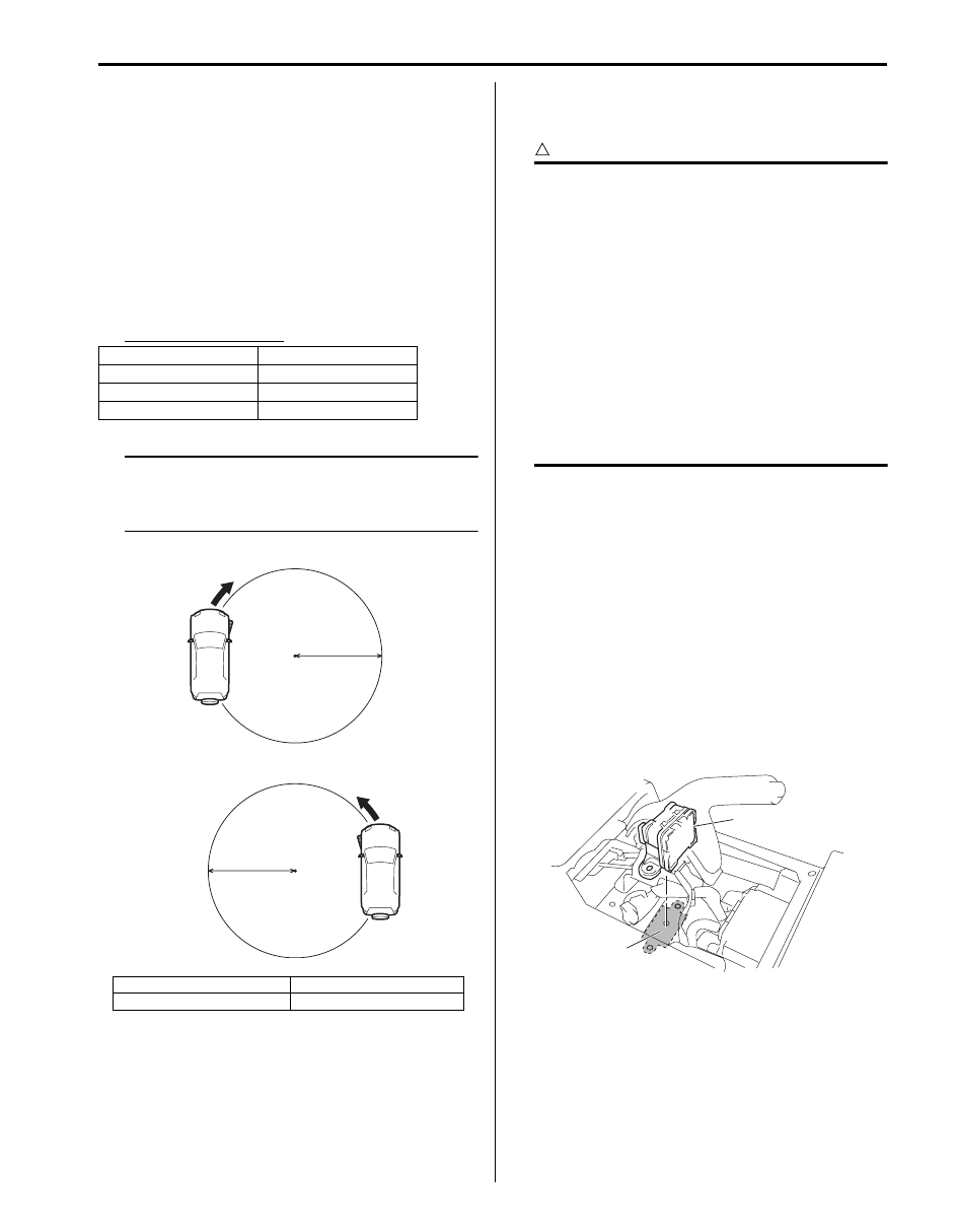
• Parking condition
• Drive vehicle in right turning condition with
steering wheel fully turned
• Drive vehicle in left turning condition with steering
wheel fully turned
If yaw rate condition is out of specification, replace
yaw rate / G sensor assembly.
Yaw rate specification
NOTE
• Drive the vehicle on level ground and at 10
km/h (6.2 mph).
• Minimum turning radius is 5.3 m (17.4 ft).
Yaw Rate / G Sensor Assembly Removal and
Installation
S6JB0B4606018
CAUTION
!
• When yaw rate / G sensor assembly is
replaced, ESP
® control module needs zero
calibration. Perform zero calibration by
SUZUKI scan tool referring to “Sensor
Calibration”.
• Regarding yaw rate / G sensor assembly
removal/installation, confirm specified
torque and never use impact wrench to
avoid damage.
• When handling the yaw rate / G sensor
assembly, be careful not to drop it or apply
an impact to it.
If an excessive impact was applied, never
attempt disassembly or repair but replace
it with a new one.
Removal
1) Disconnect negative (–) cable at battery.
2) Remove console rear panel referring to “Console
Box Components in Section 9H”.
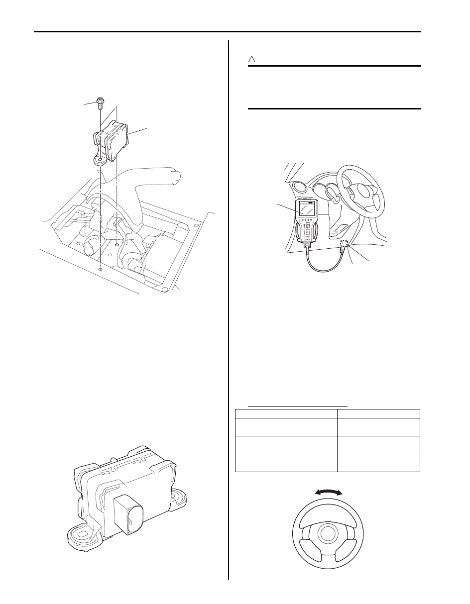
3) Remove yaw rate / G sensor assembly from floor
panel.
Installation
1) Before installing yaw rate / G sensor assembly (1),
check installing condition as follows.
• Deformations around sensor installation area (2)
(in floor panel).
• Foreign matters on mating surface between
sensor and floor panel.
Vehicle condition
Yaw rate
Parking
0
± 4 deg/s
Right turning
30
± 4 deg/s
Left turning
–30
± 4 deg/s
[A]: Right turning
“a”: Approx 5.3 m (17.4 ft.)
[B]: Left turning
[A]
[B]
“a”
“a”
I6JB01460028-01
2
1
I6JB01460029-05
4F-49 Electronic Stability Program:
2) Install yaw rate / G sensor assembly (1) to floor
panel.
Tightening torque
Yaw rate / G sensor assembly bolt (a): 8 N·m (
0.8 kgf-m, 6.0 lb-ft)
3) Install console rear panel referring to “Console Box
4) Connect negative (–) cable to battery.
5) After completing installation, calibrate yaw rate / G
sensor assembly referring to “Sensor Calibration”.
Yaw Rate / G Sensor Inspection
S6JB0B4606019
• Check sensor for dents, cracks or deformation.
• Check sensor connector (sensor side and harness
side) and sensor connector lock mechanism for
damage or crack.
• Check connector terminals for bend, corrosion or rust.
If it is found faulty, replace yaw rate / G sensor assembly.
Steering Angle Sensor On-Vehicle Inspection
S6JB0B4606020
CAUTION
!
Before each inspection, confirm steering
angle sensor calibration is completed.
If calibration is incompleted, calibrate sensor
referring to “Sensor Calibration”.
1) Connect SUZUKI scan tool to data link connector
(DLC) (1) with ignition switch OFF.
Special tool
(A): SUZUKI scan tool
2) Turn ignition switch to ON position and select menu
“DATA LIST” mode of SUZUKI scan tool.
Refer to scan tool operator's manual for further
derails.
3) Check “Steering angle Sen” under “DATA LIST” of
SUZUKI scan tool in the following steering wheel
conditions.
• Front wheels in straight-ahead position
• Rotate steering wheel a round in clockwise
(counter clockwise) from straight-ahead position
If steering angle condition is out of specification,
replace steering angle sensor.
Steering angle Specification
1
(a)
I6JB01460030-02
I6JB01460031-01
Vehicle condition
Steering angle
Front wheels in straight-
ahead position
0
± 3°
Rotate steering wheel a
round in clockwise
360
± 3°
Rotate steering wheel a
round in counterclockwise
–360
± 3°
(A)
1
I5JB0A450008-01
I6JB01460032-01
Electronic Stability Program: 4F-50
Steering Angle Sensor Removal and Installation
S6JB0B4606021
Refer to “Steering Angle Sensor Removal and
Installation (ESP
Steering Angle Sensor Inspection
S6JB0B4606022
• Check sensor for dents, cracks or deformation.
• Check sensor connector (sensor side and harness
side) and sensor connector lock mechanism for
damage or crack.
• Check connector terminals for bend, corrosion or rust.
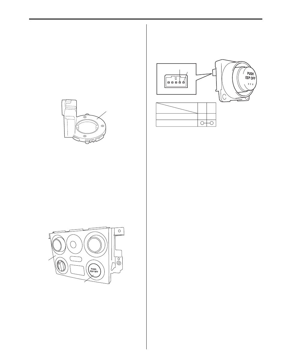
If it is found faulty, replace steering angle sensor (1).
ESP
® OFF Switch Removal and Installation
S6JB0B4606023
Removal
1) Disconnect negative (–) cable at battery.
2) Remove center garnish with audio unit (if equipped)
and HVAC control module referring to “Audio Unit
Removal and Installation in Section 9C”.
3) Remove HVAC control module from center garnish,
referring to “Air Flow Control Actuator Removal and
Installation in Section 7A”.
4) Remove ESP
® OFF Switch (1) from center garnish
(2).
Installation
Reverse removal procedure.
ESP
® OFF Switch Inspection
S6JB0B4606024
Check for continuity between terminals at each switch
position.
If check result is not as specified, replace ESP
® OFF
switch.
1
I6JB01460033-01
2
1
I6JB01460034-01
ESP OFF switch
Terminal
FREE
PUSH
1
2
2
1
I6JB01460035-02
Нет комментариевНе стесняйтесь поделиться с нами вашим ценным мнением.
Текст