Suzuki Grand Vitara JB627. Manual — part 244
5A-160 Automatic Transmission/Transaxle:
Special Tools and Equipment
Recommended Service Material
S6JB0B5108001
NOTE
Required service material is also described in the following.
“Automatic Transmission Unit Components”
“Oil Pump Assembly Components”
“Clutch Drum & Input Shaft Assembly Components”
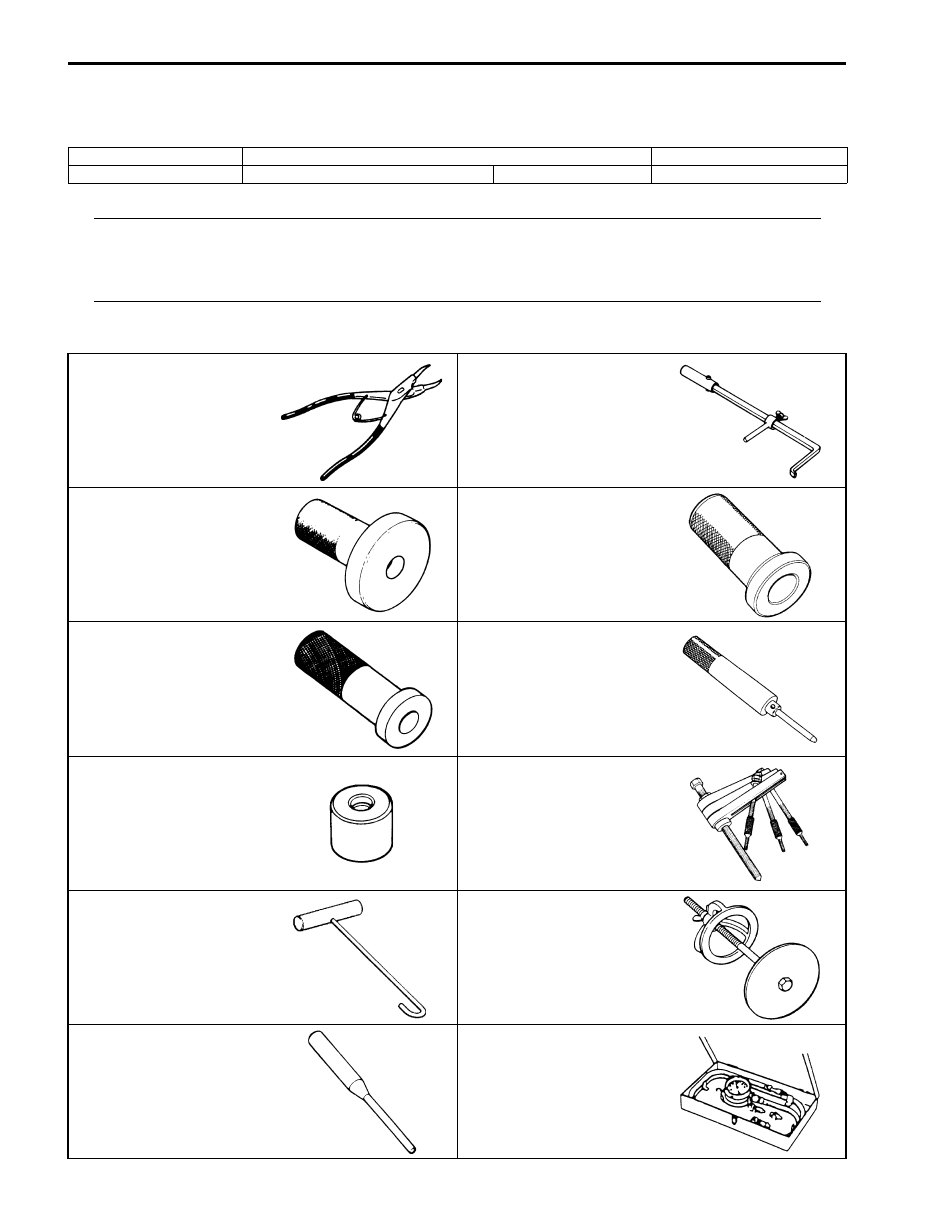
Special Tool
S6JB0B5108002
Material
SUZUKI recommended product or Specification
Note
Sealant
SUZUKI Bond No.1216B
P/No.: 99000–31230
09900–06108
09913–50121
Snap ring pliers (closing
type)
Oil seal remover
09913–75520
09913–75810
Bearing installer
Bearing installer
09913–85210
09916–57330
Bearing installer
Valve guide installer handle
09917–98221
09920–13120
Valve guide stem
attachment
Crankcase separator
09920–20310
09922–86010
Clutch spring hook
Clutch piston compressor
09922–89810
09925–37811–001
Shifter lock pin remover (3.5
mm)
Oil pressure gauge

Automatic Transmission/Transaxle: 5A-161
09926–96040
09926–96520
Clutch spring compressor
No.8
Spring compressor
09927–66510
09927–66520
Spring compressor
Oil pump remover
09927–66530
09927–66540
Spring compressor
Spring compressor
SUZUKI scan tool
—
This kit includes following
items. 1. Tech 2, 2. PCMCIA
card, 3. DLC cable, 4. SAE
16/19 adapter, 5. Cigarette
cable, 6. DLC loop back
adapter, 7. Battery power
cable, 8. RS232 cable, 9.
RS232 adapter, 10. RS232
loop back connector, 11.
Storage case, 12. ) / ) / )
5B-1 Manual Transmission/Transaxle:
Transmission / Transaxle
Manual Transmission/Transaxle
General Description
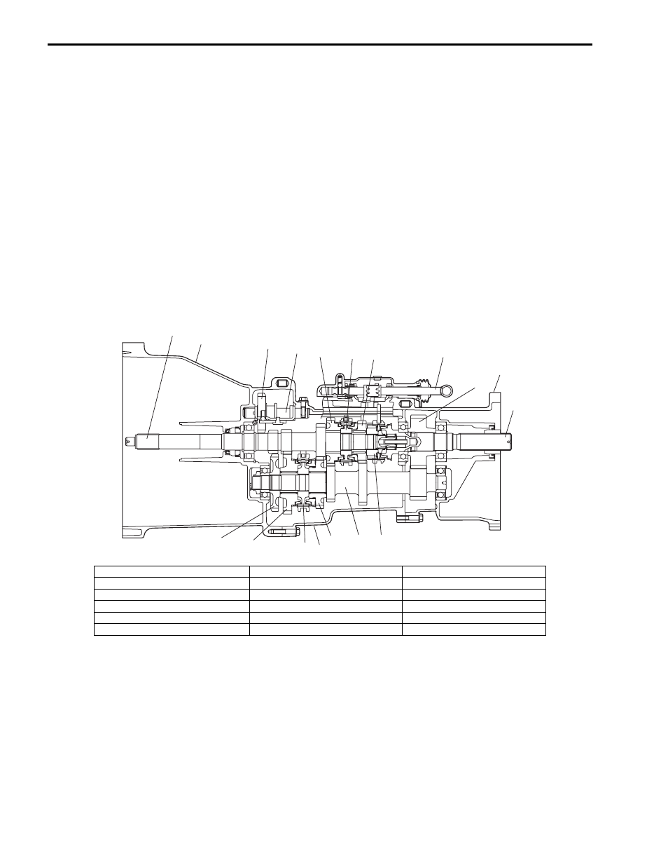
Manual Transmission Construction
S6JB0B5201001
The manual transmission consists of the input shaft, output shaft, countershaft and reverse idle gear shaft which are
installed in the die-cast aluminum alloy case. This transmission provides five forward speeds and one reverse speed.
The 1st, 2nd, 3rd and 4th speeds are for speed reduction drive, 5th speed is for direct drive. The low speed (1st and
2nd) synchronizer is mounted on the countershaft and engaged with the countershaft 1st or 2nd gear. The high speed
(3rd and 4th) synchronizer is mounted on of the input shaft and engaged with the input shaft 3rd and 4th gear. The 5th
speed synchronizer is mounted on the input shaft and engaged with the output shaft. The gear shift lever case is
located at the upper behind the transmission case and has a cam which prevents direct gear shifting from the 5th
speed gear into the reverse gear.
As the die-cast aluminum alloy case are sealed with liquid type gasket, it is necessary to use genuine sealant or its
equivalent on its mating surface when reassembling them. Also, the case fastening bolts must be tightened to
specified torque by means of the torque wrench and tightening over or below the specified torque should be avoided.
The description under “Repair Instructions” covers the transfer partially which is next to the transmission as well, but
their gear boxes are independent and each of them has its own drain and filler plugs for the oil change or the level
check.
1
2
3
4
5
6
7
8
9
10
11
12
13
14
15
16
17
18
I5JB0A520017-02
1. Input shaft
7. 3rd gear
13. Countershaft
2. Transmission front case
8. Gear shift shaft
14. 2nd gear
3. Reverse idler gear
9. Output shaft gear
15. Transmission rear case
4. Reverse shaft
10. Adapter case
16. Low speed synchronizer hub
5. 4th gear
11. Output shaft
17. 1st gear
6. High speed synchronizer hub
12. 5th speed synchronizer hub
18. Reverse gear
Manual Transmission/Transaxle: 5B-2
Diagnostic Information and Procedures
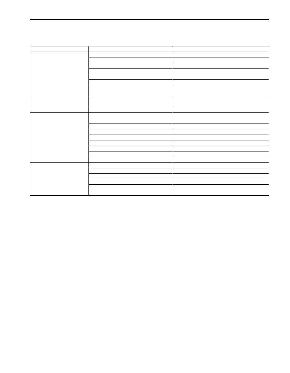
Manual Transmission Symptom Diagnosis
S6JB0B5204001
Condition
Possible cause
Correction / Reference Item
Gear slipping out of mesh Worn shift fork shaft
Replace.
Worn shift fork or synchronizer sleeve
Replace.
Weak or damaged locating spring
Replace.
Worn bearings on input shaft,
countershaft or output shaft
Replace.
Worn chamfered tooth on sleeve or gear Replace sleeve and gear.
Missing or disengagement of snap
ring(s)
Install or replace.
Gears refusing to
disengage
Weakened or broken synchronizer
spring
Replace.
Distorted shift shaft or shift fork
Replace.
Hard shifting
Improper clutch pedal free travel
Replace pedal arm and/or clutch master
cylinder.
Distorted or broken clutch disc
Replace.
Damaged clutch pressure plate
Replace clutch cover.
Air in clutch hydraulic system
Bleed air.
Fluid leakage from clutch fluid line
Locate leaking point and repair.
Worn synchronizer ring
Replace.
Worn chamfered tooth on sleeve or gear Replace sleeve and gear.
Distorted shift shaft
Replace.
Noise
Inadequate or insufficient lubricant
Replenish.
Damaged or worn bearing(s)
Replace.
Damaged or worn gear(s)
Replace.
Damaged or worn synchronizer ring
Replace.
Damaged or worn chamfered tooth on
sleeve or gear
Replace.
Нет комментариевНе стесняйтесь поделиться с нами вашим ценным мнением.
Текст