Suzuki Grand Vitara JB627. Manual — part 243
5A-156 Automatic Transmission/Transaxle:
• Measure planetary pinion gear thrust clearance by
using thickness gauge.
If clearance exceeds limit, replace middle planetary
gear assembly.
Middle planetary pinion gear thrust clearance
Standard: 0.12 – 0.68 mm (0.005 – 0.027 in.)
Limit: 0.73 mm (0.029 in.)
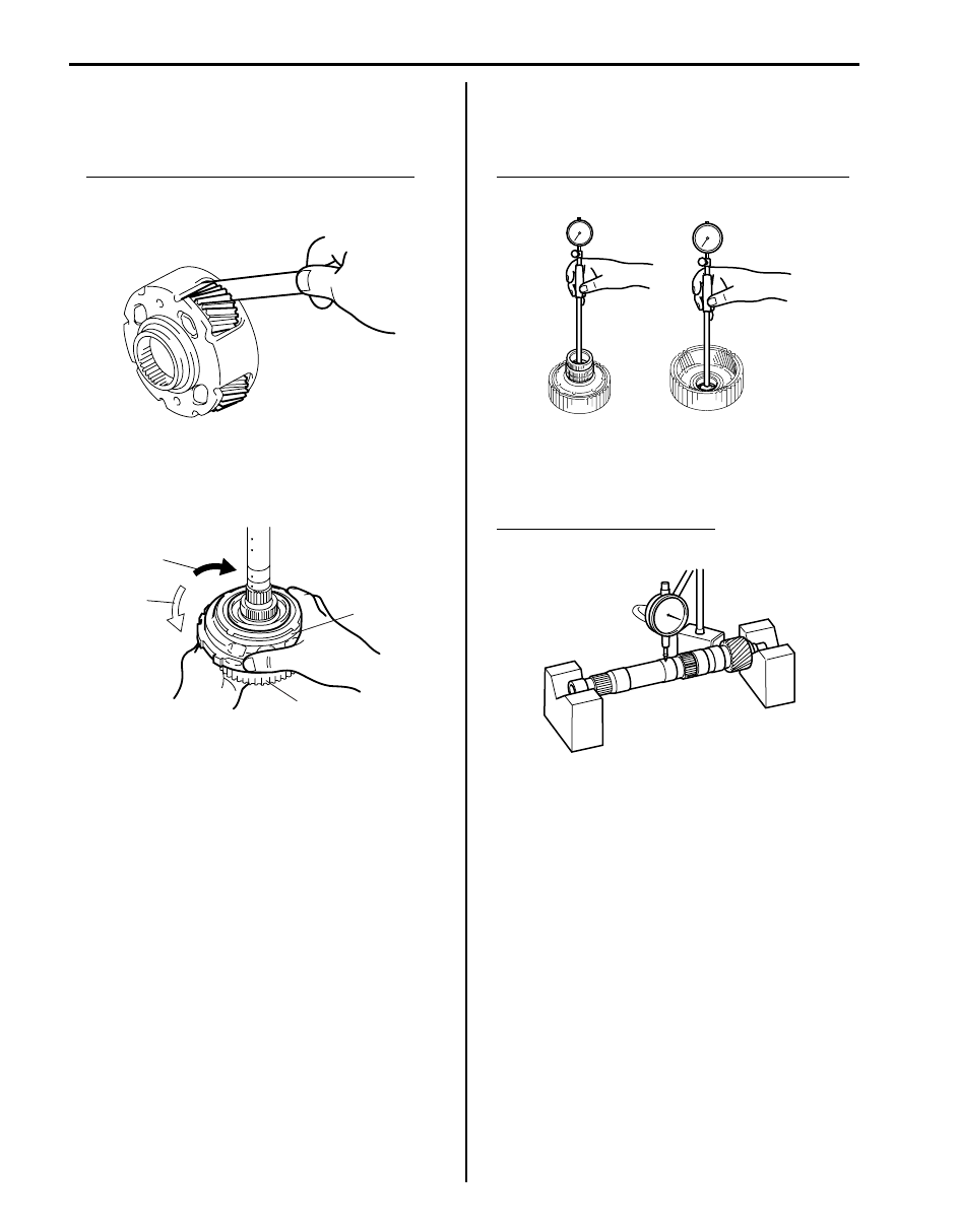
• Hold rear planetary ring gear flange sub assembly (1)
and turn one-way No.3 clutch assembly (2). Check
that one-way No.3 clutch assembly (2) can be turned
freely (3) counterclockwise and locked (4) clockwise.
• Measure inside diameter of planetary ring gear
assembly bushing.
If inside diameter exceeds limit, replace planetary ring
gear.
Planetary ring gear bushing inside diameter limit
32.19 mm (1.267 in.)
• Set intermediate shaft between two “V” blocks, and
measure its runout by using a dial gauge.
If runout exceeds limit, replace intermediate shaft with
new one.
Intermediate shaft runout limit
0.08 mm (0.003 in.)
I4JA01512307-01
4
3
1
2
I4JA01512308-01
I4JA01512309-01
I4JA01512310-01
Automatic Transmission/Transaxle: 5A-157
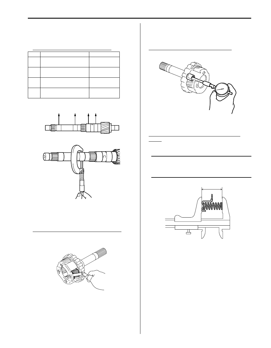
• Measure outside diameter of intermediate shaft
positions shown in figure.
If outside diameter is below limit, replace intermediate
shaft with new one.
Outside diameter of intermediate shaft
• Measure planetary pinion gear thrust clearance by
using thickness gauge.
If clearance exceeds limit, replace rear planetary gear
assembly.
Rear planetary pinion gear thrust clearance
Standard: 0.2 – 0.6 mm (0.008 – 0.024 in.)
Limit: 0.65 mm (0.026 in.)
• Measure inside diameter of rear planetary gear
assembly bushing.
If inside diameter exceeds limit, replace rear planetary
gear assembly.
Rear planetary gear inside diameter limit
20.075 mm (0.790 in.)
• Measure free length of 1st & reverse (No.4) brake
return spring including spring seat.
1st & reverse (No.4) brake return spring free
length
“a”: 23.74 mm (0.935 in.)
NOTE
• Do not apply excessive force when
measuring spring free length.
• Perform measurement at several points.
Standard
Limit
A
25.962 – 25.975 mm
(1.022 – 1.023 in.)
25.912 mm
(1.020 in.)
B
25.962 – 25.975 mm
(1.022 – 1.023 in.)
25.912 mm
(1.020 in.)
C
32.062 – 32.075 mm
(1.262 – 1.263 in.)
32.012 mm
(1.260 in.)
D
32.062 – 32.075 mm
(1.262 – 1.263 in.)
32.012 mm
(1.260 in.)
A
B
C
D
I5JA01512007-01
I4JA01512312-01
I4JA01512313-01
“a”
I4JA01512314-01
5A-158 Automatic Transmission/Transaxle:
Specifications
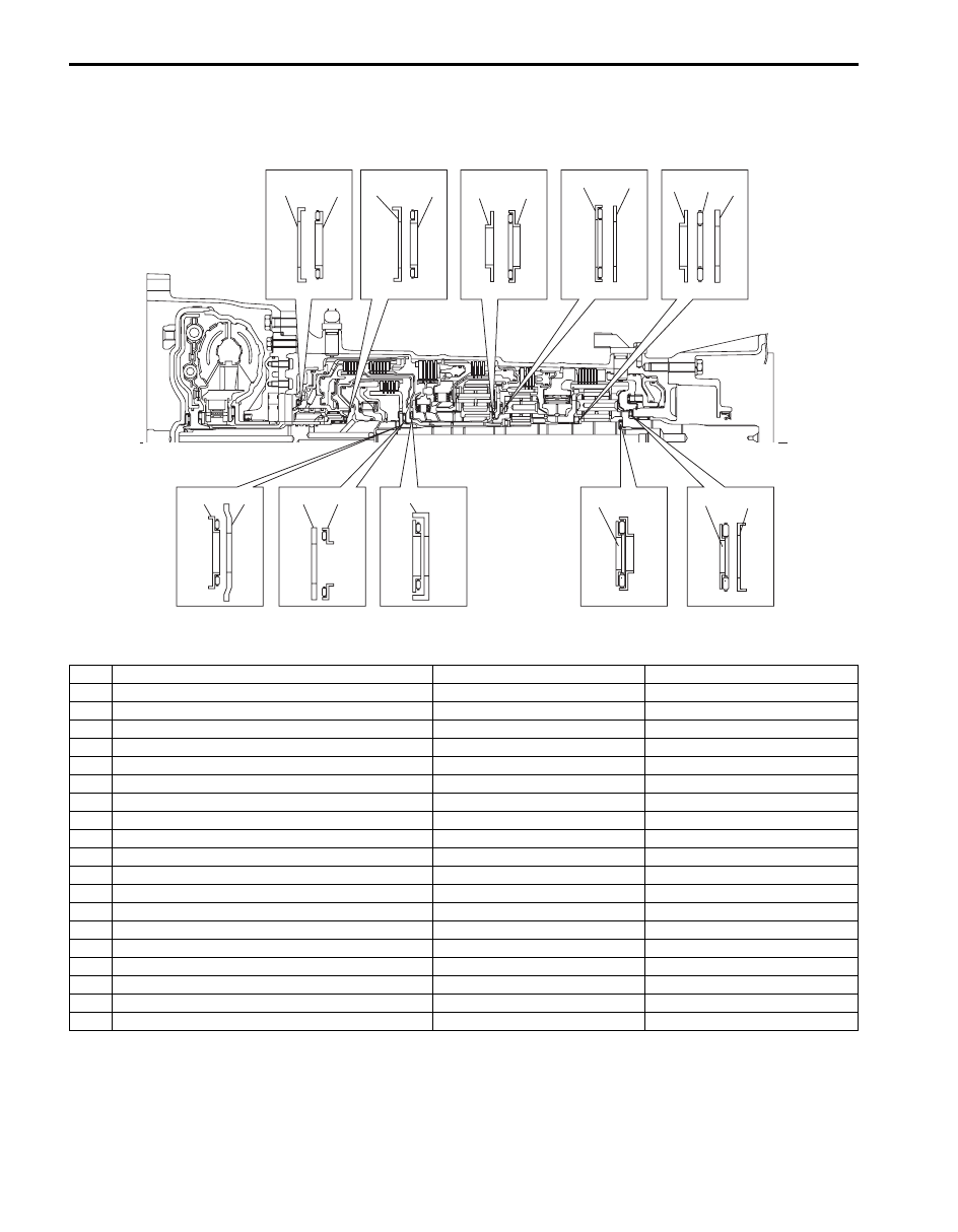
Bearing and Race Installation Specification
S6JB0B5107001
Bearing and Race Dimension
14
15
16
12
13
10
11
1
2
3
4
9
7
8
5
6
17
18
19
I6JB01510047-04
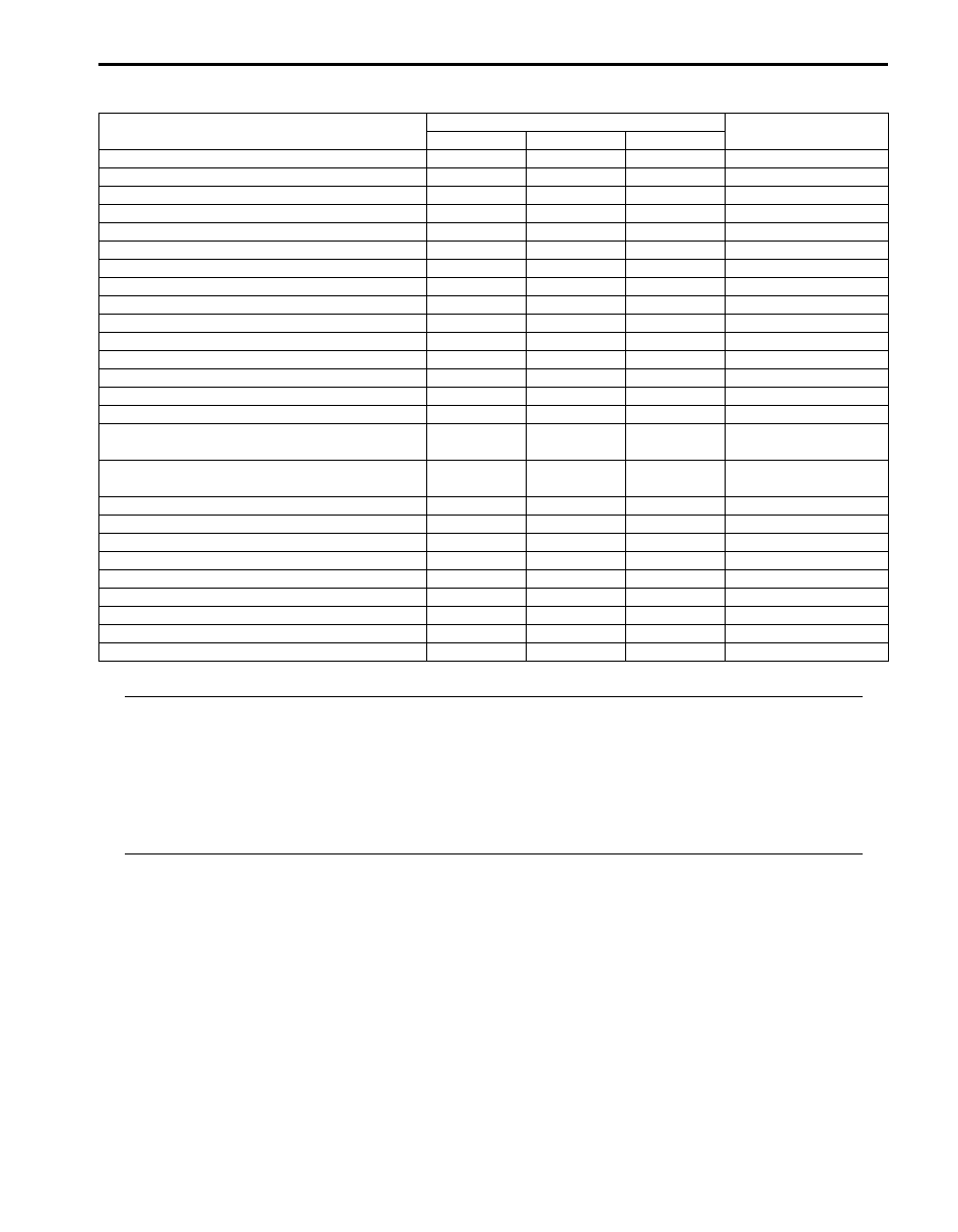
No.
Bearing and race
Inside diameter
Outside diameter
1
Thrust bearing race No.1
74.2 mm (2.921 in.)
87.74 mm (3.454 in.)
2
Thrust needle roller bearing
71.9 mm (2.831 in.)
85.6 mm (3.370 in.)
3
Thrust bearing race No.10
37.1 mm (1.461 in.)
52.2 mm (2.055 in.)
4
Thrust needle roller bearing
34.7 mm (1.366 in.)
52.1 mm (2.055 in.)
5
Thrust needle roller bearing
21.3 mm (0.839 in.)
41.1 mm (1.618 in.)
6
Thrust bearing race
22.6 mm (0.890 in.)
60.0 mm (2.362 in.)
7
Thrust bearing race No.2
38.4 mm (1.512 in.)
63.0 mm (2.480 in.)
8
Thrust needle roller bearing
42.5 mm (1.673 in.)
61.2 mm (2.409 in.)
9
Thrust needle roller bearing
33.3 mm (1.311 in.)
56.6 mm (2.228 in.)
10 Thrust bearing race No.3
38.0 mm (1.496 in.)
57.0 mm (2.244 in.)
11 Thrust needle roller bearing
43.4 mm (1.709 in.)
58.3 mm (2.295 in.)
12 Thrust needle roller bearing
55.7 mm (2.193 in.)
76.4 mm (3.008 in.)
13 Thrust bearing race No.4
53.7 mm (2.114 in.)
74.0 mm (2.913 in.)
14 Thrust bearing race No.7
33.4 mm (1.315 in.)
49.0 mm (1.929 in.)
15 Thrust needle roller bearing
32.1 mm (1.264 in.)
49.35 mm (1.943 in.)
16 Thrust bearing race No.8
32.1 mm (1.264 in.)
49.0 mm (1.929 in.)
17 Thrust needle roller bearing
21.5 mm (0.847 in.)
40.8 mm (1.606 in.)
18 Thrust needle roller bearing
48.5 mm (1.909 in.)
62.7 mm (2.469 in.)
19 Thrust bearing race No.9
45.9 mm (1.807 in.)
64.0 mm (2.520 in.)
Automatic Transmission/Transaxle: 5A-159
Tightening Torque Specifications
S6JB0B5107002
NOTE
The specified tightening torque is also described in the following.
“Oil Cooler Hoses Replacement”
“Manual Selector Assembly Components”
“Select Cable Component”
“Automatic Transmission Unit Components”
“Automatic Transmission Unit Components”
“Oil Pump Assembly Components”
“Valve Body Assembly Components”
Reference:
For the tightening torque of fastener not specified in this section, refer to “Fastener Information in Section 0A”.
Fastening part
Tightening torque
Note
N
⋅m
kgf-m
lb-ft
Fluid pressure check hole bolt
8
0.8
6.0
A/T fluid drain plug
20
2.0
14.5
Manual selector assembly mounting bolt
18
1.8
13.0
Manual select cable end nut
13
1.3
9.5
Manual shift shaft nut
7
0.7
5.0
Transmission range sensor bolt
13
1.3
9.5
Input shaft speed sensor bolt
5.5
0.55
4.0
Output shaft speed sensor bolt
5.5
0.55
4.0
Oil cooler pipe union bolt
25
2.5
18.0
Pipe clamp bolt
10
1.0
7.5
Oil pump body bolt
11
1.1
8.0
Oil pump bolt
21
2.1
15.0
Parking pawl bracket bolt
7.4
0.74
5.5
Valve body bolt
11
1.1
8.0
Transmission wire connector bolt
5.5
0.55
4.0
Transmission fluid temperature sensor clamp
bolt
11
1.1 8.0
Transmission fluid temperature sensor clamp
bolt
10
1.0 7.0
Oil strainer bolt
10
1.0
7.0
Oil pan bolt
4.5
0.45
3.5
Drain plug
20
2.0
14.5
Transmission case adapter sub assembly bolt
34
3.4
24.5
Automatic transmission housing bolt
57
5.7
41.5
Automatic transmission housing bolt
34
3.4
24.5
Automatic transmission breather pipe bolt
5.5
0.55
4.0
Transmission speed sensor bolt
5.5
0.55
4.0
Manual select lever nut
12.5
1.25
9.0
Нет комментариевНе стесняйтесь поделиться с нами вашим ценным мнением.
Текст