Suzuki Grand Vitara JB627. Manual — part 67
1A-217 Engine General Information and Diagnosis:
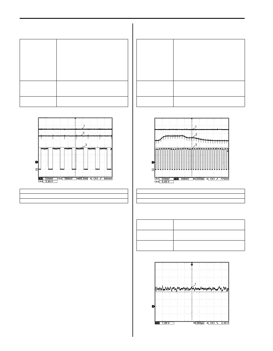
Reference waveform No.10
A/F sensor heater and A/F sensor signals (Bank-1 and
Bank-2):
Reference waveform No.11
A/F sensor heater and A/F sensor signals (Bank-1 and
Bank-2):
Reference waveform No.12
Knock sensor signal (1):
Measurement
terminal
Bank-1
CH1: C37-18 to C37-81
CH2: C37-19 to C37-81
CH3: C37-77 to C37-81
Bank-2
CH1: C37-37 to C37-81
CH2: C37-38 to C37-81
CH3: C37-78 to C37-81
Oscilloscope
setting
CH1: 500 mV/DIV, CH2: 500 mV/
DIV, CH3: 5 V/DIV
TIME: 40 ms/DIV
Measurement
condition
Engine is running at specified idle
speed after warmed up engine.
1. A/F sensor (+) signal
2. A/F sensor (–) signal
3. A/F sensor heater signal
I6JB01110074-02
Measurement
terminal
Bank-1
CH1: C37-18 to C37-81
CH2: C37-19 to C37-81
CH3: C37-77 to C37-81
Bank-2
CH1: C37-37 to C37-81
CH2: C37-38 to C37-81
CH3: C37-78 to C37-81
Oscilloscope
setting
CH1: 500 mV/DIV, CH2: 500 mV/
DIV, CH3: 5 V/DIV
TIME: 200 ms/DIV
Measurement
condition
Engine is racing after warmed up
engine.
1. A/F sensor (+) signal
2. A/F sensor (–) signal
3. A/F sensor heater signal
Measurement
terminal
CH1: C37-25 to C37-81
Oscilloscope
setting
CH1: 1 V/DIV
TIME: 200
µs/DIV
Measurement
condition
Engine is running at 4000 rpm after
warmed up engine.
I6JB01110075-02
I6JB01110076-02
Engine General Information and Diagnosis: 1A-218
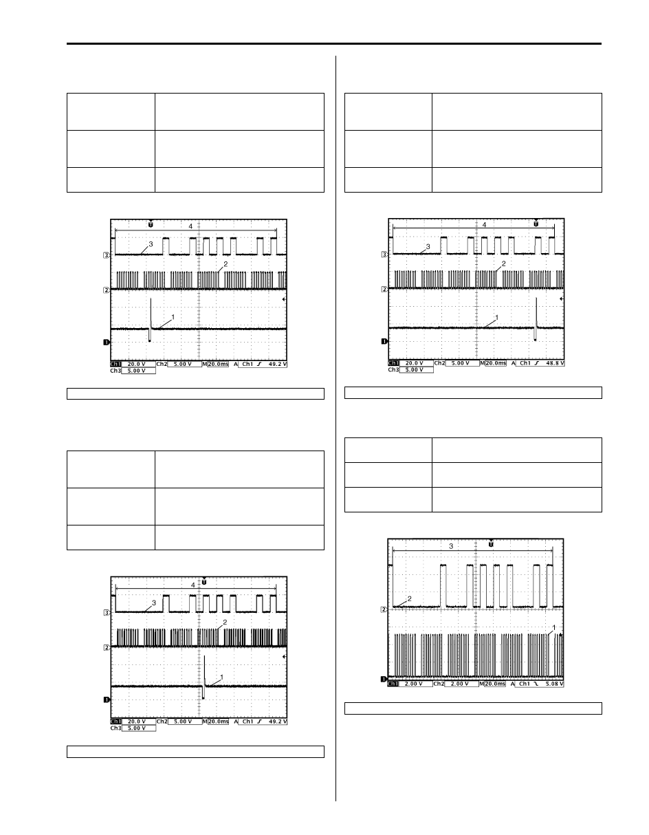
Reference waveform No.13
Fuel injector No.6 (1), CKP sensor (2) and CMP sensor
(3) signals:
Reference waveform No.14
Fuel injector No.4 (1), CKP sensor (2) and CMP sensor
(3) signals:
Reference waveform No.15
Fuel injector No.2 (1), CKP sensor (2) and CMP sensor
(3) signals:
Reference waveform No.16
CKP sensor (1) and CMP sensor (2) signals:
Measurement
terminal
CH1: C37-32 to C37-81
CH2: C37-47 to C37-81
CH3: C37-66 to C37-81
Oscilloscope
setting
CH1: 20 V/DIV, CH2: 5 V/DIV,
CH3: 5 V/DIV
TIME: 20 ms/DIV
Measurement
condition
Engine is running at specified idle
speed after warmed up engine.
4. 720
° crank angle
Measurement
terminal
CH1: C37-33 to C37-81
CH2: C37-47 to C37-81
CH3: C37-66 to C37-81
Oscilloscope
setting
CH1: 20 V/DIV, CH2: 5 V/DIV,
CH3: 5 V/DIV
TIME: 20 ms/DIV
Measurement
condition
Engine is running at specified idle
speed after warmed up engine.
4. 720
° crank angle
I6JB01110077-02
I6JB01110078-02
Measurement
terminal
CH1: C37-34 to C37-81
CH2: C37-47 to C37-81
CH3: C37-66 to C37-81
Oscilloscope
setting
CH1: 20 V/DIV, CH2: 5 V/DIV,
CH3: 5 V/DIV
TIME: 20 ms/DIV
Measurement
condition
Engine is running at specified idle
speed after warmed up engine.
4. 720
° crank angle
Measurement
terminal
CH1: C37-47 to C37-81
CH2: C37-66 to C37-81
Oscilloscope
setting
CH1: 2 V/DIV, CH2: 2 V/DIV,
TIME: 20 ms/DIV
Measurement
condition
Engine is running at specified idle
speed after warmed up engine.
3. 720
° crank angle
I6JB01110079-02
I6JB01110080-02
1A-219 Engine General Information and Diagnosis:
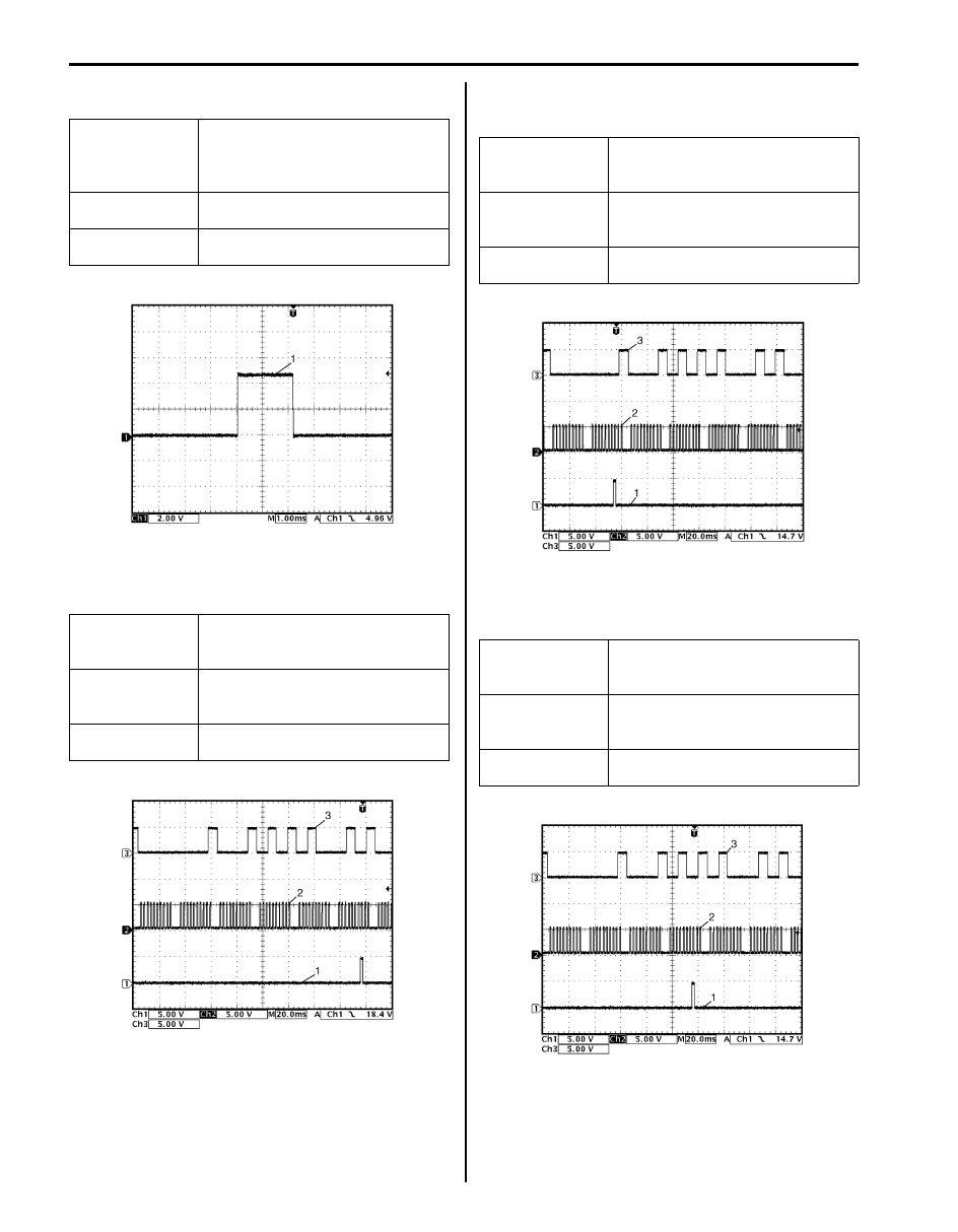
Reference waveform No.17
Ignition coil signal (1):
Reference waveform No.18
Ignition coil No.5 (1), CKP sensor (2) and CMP sensor
(3) signals:
Reference waveform No.19
Ignition coil No.3 (1), CKP sensor (2) and CMP sensor
(3) signals:
Reference waveform No.20
Ignition coil No.1 (1), CKP sensor (2) and CMP sensor
(3) signals:
Measurement
terminal
CH1: C37-57 (No.1), C37-76 (No.2),
C37-56 (No.3), C37-75 (No.4), C37-
55 (No.5) or C37-74 (No.6) to C37-
81
Oscilloscope
setting
CH1: 2 V/DIV
TIME: 1 ms/DIV
Measurement
condition
Engine is running at specified idle
speed after warmed up engine.
Measurement
terminal
CH1: C37-55 to C37-81
CH2: C37-47 to C37-81
CH3: C37-66 to C37-81
Oscilloscope
setting
CH1: 5 V/DIV, CH2: 5 V/DIV,
CH3: 5 V/DIV
TIME: 20 ms/DIV
Measurement
condition
Engine is running at specified idle
speed after warmed up engine.
I6JB01110081-02
I6JB01110108-02
Measurement
terminal
CH1: C37-56 to C37-81
CH2: C37-47 to C37-81
CH3: C37-66 to C37-81
Oscilloscope
setting
CH1: 5 V/DIV, CH2: 5 V/DIV,
CH3: 5 V/DIV
TIME: 20 ms/DIV
Measurement
condition
Engine is running at specified idle
speed after warmed up engine.
Measurement
terminal
CH1: C37-57 to C37-81
CH2: C37-47 to C37-81
CH3: C37-66 to C37-81
Oscilloscope
setting
CH1: 5 V/DIV, CH2: 5 V/DIV,
CH3: 5 V/DIV
TIME: 20 ms/DIV
Measurement
condition
Engine is running at specified idle
speed after warmed up engine.
I6JB01110082-02
I6JB01110084-02
Engine General Information and Diagnosis: 1A-220
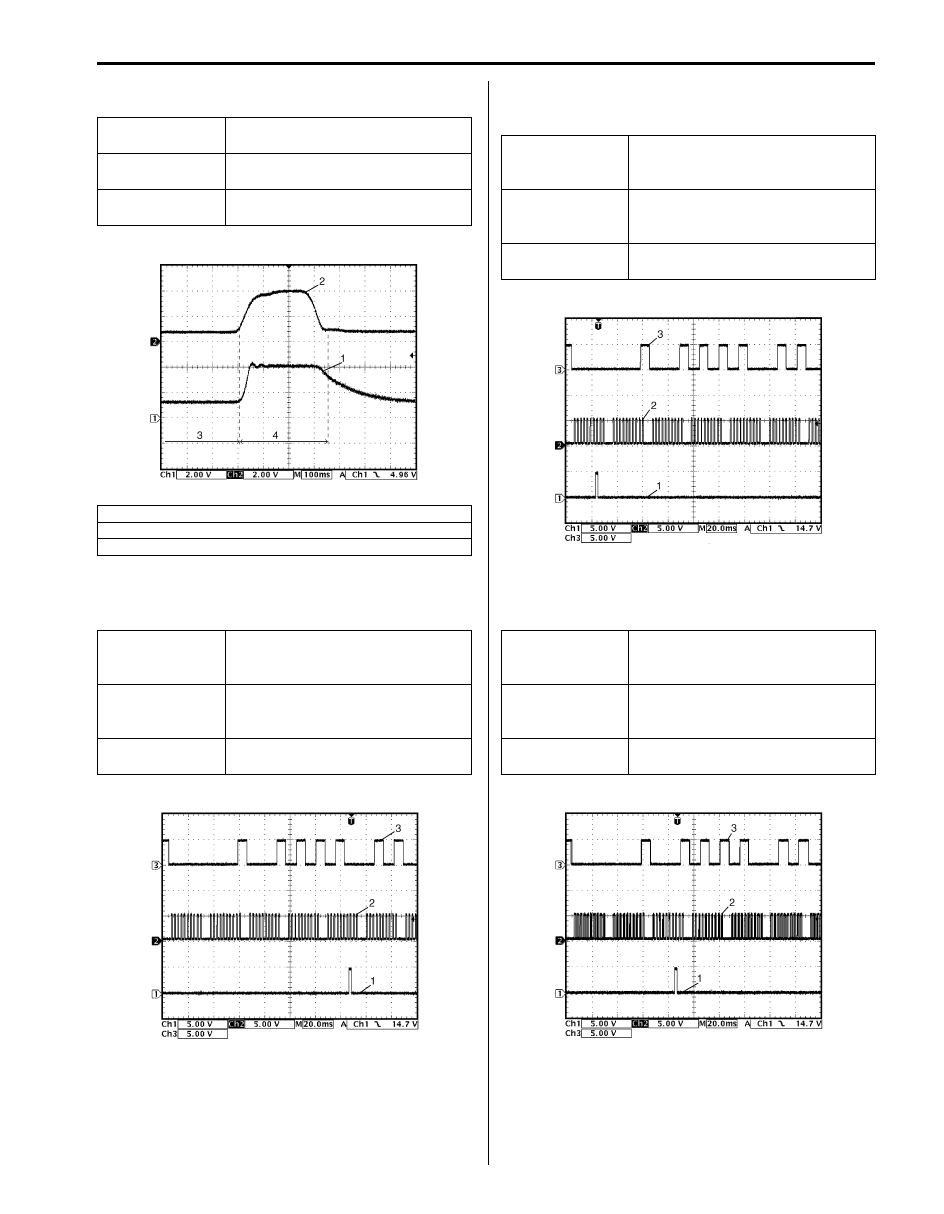
Reference waveform No.21
MAP sensor signal (1):
Reference waveform No.22
Ignition coil No.6 (1), CKP sensor (2) and CMP sensor
(3) signals:
Reference waveform No.23
Ignition coil No.4 (1), CKP sensor (2) and CMP sensor
(3) signals:
Reference waveform No.24
Ignition coil No.2 (1), CKP sensor (2) and CMP sensor
(3) signals:
Measurement
terminal
CH1: C37-68 to C37-67
CH2: C37-46 to C37-81
Oscilloscope
setting
CH1: 2 V/DIV, CH2: 2 V/DIV
TIME: 100 ms/DIV
Measurement
condition
Engine is racing after warmed up
engine.
2. Throttle position sensor (main) signal
3. Idle
4. Racing
Measurement
terminal
CH1: C37-74 to C37-81
CH2: C37-47 to C37-81
CH3: C37-66 to C37-81
Oscilloscope
setting
CH1: 5 V/DIV, CH2: 5 V/DIV,
CH3: 5 V/DIV
TIME: 20 ms/DIV
Measurement
condition
Engine is running at specified idle
speed after warmed up engine.
I6JB01110083-02
I6JB01110085-02
Measurement
terminal
CH1: C37-75 to C37-81
CH2: C37-47 to C37-81
CH3: C37-66 to C37-81
Oscilloscope
setting
CH1: 5 V/DIV, CH2: 5 V/DIV,
CH3: 5 V/DIV
TIME: 20 ms/DIV
Measurement
condition
Engine is running at specified idle
speed after warmed up engine.
Measurement
terminal
CH1: C37-76 to C37-81
CH2: C37-47 to C37-81
CH3: C37-66 to C37-81
Oscilloscope
setting
CH1: 5 V/DIV, CH2: 5 V/DIV
CH3: 5 V/DIV
TIME: 20 ms/DIV
Measurement
condition
Engine is running at specified idle
speed after warmed up engine.
I6JB01110086-01
I6JB01110087-02
Нет комментариевНе стесняйтесь поделиться с нами вашим ценным мнением.
Текст