Suzuki Grand Vitara JB627. Manual — part 68
1A-221 Engine General Information and Diagnosis:
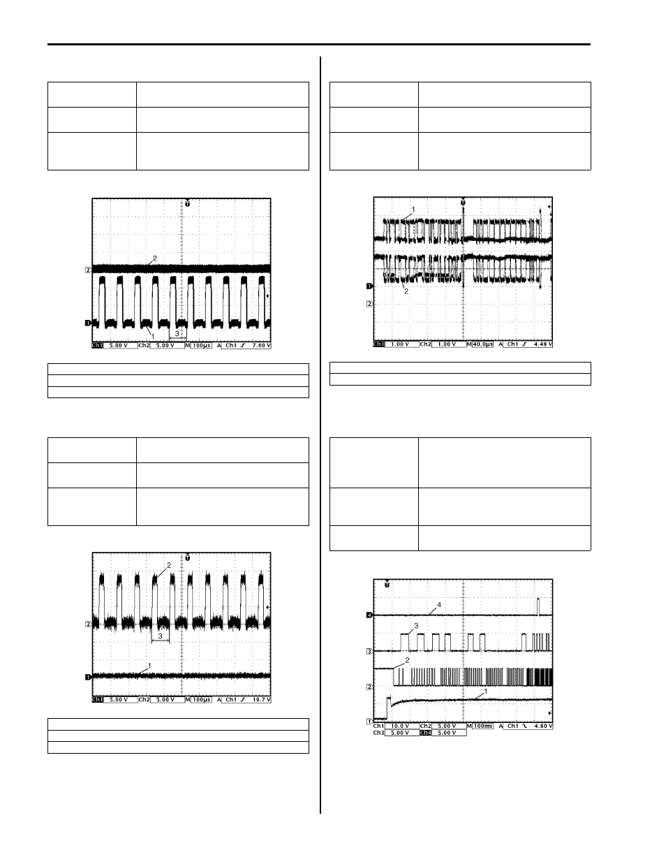
Reference waveform No.25
Throttle actuator output signals:
Reference waveform No.26
Throttle actuator output signals:
Reference waveform No.27
CAN communication line signals:
Reference waveform No.28
Start (1), CKP sensor (2), CMP sensor (3) and ignition
coil No.1 (4) signals:
Measurement
terminal
CH1: E23-4 to C37-81
CH2: E23-5 to C37-81
Oscilloscope
setting
CH1: 5 V/DIV, CH2: 5 V/DIV,
TIME: 100
µs/DIV
Measurement
condition
Ignition switch is at ON position and
accelerator pedal is not depressed
after warmed up engine.
1. Throttle actuator drive signal (E23-4 terminal)
2. Throttle actuator drive signal (E23-5 terminal)
3. One duty cycle
Measurement
terminal
CH1: E23-4 to C37-81
CH2: E23-5 to C37-81
Oscilloscope
setting
CH1: 5 V/DIV, CH2: 5 V/DIV
TIME: 100
µs/DIV
Measurement
condition
Ignition switch is at ON position and
accelerator pedal is at fully
depressed after warmed up engine.
1. Throttle actuator drive signal (E23-4 terminal)
2. Throttle actuator drive signal (E23-5 terminal)
3. One duty cycle
I6JB01110088-01
I6JB01110089-02
Measurement
terminal
CH1: E23-9 to C37-81
CH2: E23-17 to C37-81
Oscilloscope
setting
CH1: 1 V/DIV, CH2: 1V/DIV
TIME: 40
µs/DIV
Measurement
condition
Ignition switch is at ON position.
(Signal pattern is depending on
communication data.)
1. CAN communication line signal (high)
2. CAN communication line signal (low)
Measurement
terminal
CH1: C37-28 to C37-81
CH2: C37-47 to C37-81
CH3: C37-66 to C37-81
CH4: C37-15 to C37-81
Oscilloscope
setting
CH1: 10 V/DIV, CH2: 5 V/DIV,
CH3: 5 V/DIV, CH4: 5 V/DIV
TIME: 100 ms/DIV
Measurement
condition
Engine is at cranking.
I6JB01110090-02
I6JB01110093-02
Engine General Information and Diagnosis: 1A-222
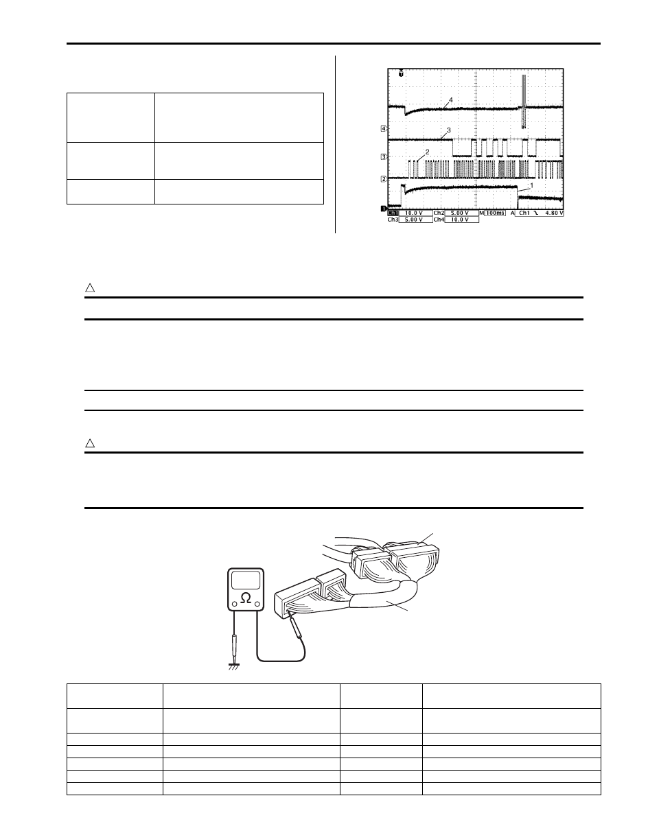
Reference waveform No.29
Start (1), CKP sensor (2), CMP sensor (3) and fuel
injector No.1 (4) signals:
Resistance Check
1) Remove ECM from its bracket referring to “Engine Control Module (ECM) Removal and Installation in Section 1C”.
CAUTION
!
Never touch terminals of ECM itself or connect voltmeter or ohmmeter (2).
2) Connect special tool (A) to ECM connectors (1) securely.
Special tool
(A): 09933–06520
NOTE
Do not connect the other connector of special tool to ECM.
3) Check resistance between each pair of terminals of special tool connectors as listed in the following table.
CAUTION
!
• Be sure to connect ohmmeter probe from wire harness side of coupler.
• Be sure to turn OFF ignition switch for this check.
• Resistance in the following table represents that measured when parts temperature is 20
°C (68 °F).
Measurement
terminal
CH1: C37-28 to C37-81
CH2: C37-47 to C37-81
CH3: C37-66 to C37-81
CH4: C37-15 to C37-81
Oscilloscope
setting
CH1: 10 V/DIV, CH2: 5 V/DIV,
CH3: 5 V/DIV, CH4: 10 V/DIV
TIME: 100 ms/DIV
Measurement
condition
Engine is at cranking.
I6JB01110094-02
1
(A)
I6JB01110116-02
Terminals
Circuit
Standard
resistance
Condition
E23-16 to E23-8
Main relay
160 – 240
Ω
Battery disconnected and ignition
switch turned ON
E23-24 to E23-8
Fuel pump relay
160 – 240
Ω
—
E23-6 to E23-8
Throttle actuator control relay
160 – 240
Ω
—
C37-15 to E23-2/3
Fuel injector No.1
10 – 14
Ω
—
C37-34 to E23-2/3
Fuel injector No.2
10 – 14
Ω
—
C37-14 to E23-2/3
Fuel injector No.3
10 – 14
Ω
—
1A-223 Engine General Information and Diagnosis:
ECM Power and Ground Circuit Check
S6JB0B1104085
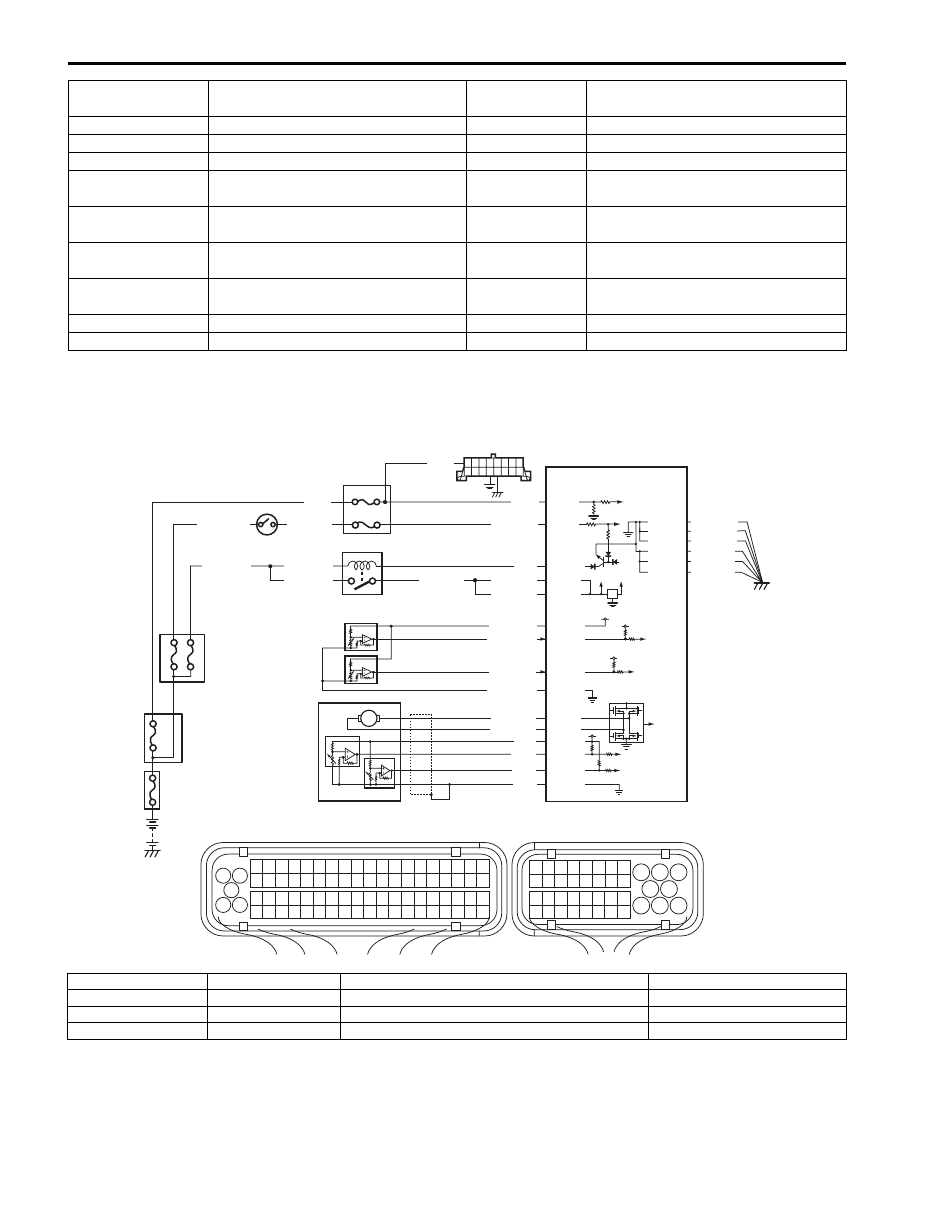
Wiring Diagram
Circuit Description
When the ignition switch is turned ON, the main relay turns ON (the contact point closes) and the main power is
supplied to ECM. And then ECM supplies 5 V power to each sensor (MAP sensor, A/C refrigerant pressure sensor, TP
sensor).
If 5 V power circuit to each sensors from ECM is shorted to ground, ECM stops engine and emission control operation.
C37-33 to E23-2/3
Fuel injector No.4
10 – 14
Ω
—
C37-13 to E23-2/3
Fuel injector No.5
10 – 14
Ω
—
C37-32 to E23-2/3
Fuel injector No.6
10 – 14
Ω
—
C37-12 to E23-2/3
EGR valve (stepping motor No.1 coil)
(if equipped)
20 – 24
Ω
—
C37-31 to E23-2/3
EGR valve (stepping motor No.2 coil)
(if equipped)
20 – 24
Ω
—
C37-11 to E23-2/3
EGR valve (stepping motor No.3 coil)
(if equipped)
20 – 24
Ω
—
C37-30 to E23-2/3
EGR valve (stepping motor No.4 coil)
(if equipped)
20 – 24
Ω
—
C37-10 to E23-2/3
EVAP canister purge valve
25 – 30
Ω
—
C37-29 to E23-2/3
IMT vacuum solenoid valve
33 – 45
Ω
—
Terminals
Circuit
Standard
resistance
Condition
BLU/BLK
BLU/BLK
BLU/BLK
BLK/RED
BLK/RED
BLK/RED
BLU
12V 5V
2
1
14
4
3
6
10
11
12
WHT
E23-1
E23-8
E23-16
C37-49
C37-68
C37-48
C37-67
E23-2
E23-3
E23-5
E23-4
WHT/GRN
GRY/RED
RED/WHT
GRY/BLK
GRY/GRN
BLU/YEL
BLU/RED
5
C37-59
C37-58
C37-39
C37-73
C37-80
BLK/YEL
BLK/ORN
BLK/ORN
BLK/YEL
BLK/YEL
BLK
WHT
GRN
RED
WHT
WHT
8
7
1
3 2
4
5
6
7
8
9
1110
12
13
14
15
16
17
18
19
20
17
18
19
20
21
22
23
24
25
26
27
28
29
30
31
33
34
35
36
37
38
39
40
32
1
2
3
4
5
6
7
8
9
10
11
12
13
14
15
16
21
22
23
24
25
26
27
28
29
30
31
32
33
34
35
36
37
38
39
40
41
42
43
44
45
46
47
48
49
50
51
52
53
54
55
56
57
58
59
60
61
62
63
64
65
66
67
68
69
70
71
72
73
74
75
76
77
78
79
80
81
9
C37-45
C37-46
C37-65
C37-64
E23
C37
BLK/ORN
C37-81
BLK/YEL
BLK/WHT
13
15
I5JB0C110015-01
1. Fuse box No.2
5. “IG COIL” fuse
9. “DOME” fuse
13. Throttle actuator motor
2. Ignition switch
6. ECM
10. DLC
14. TP sensor (main)
3. Main relay
7. “IG ACC” fuse
11. MAP sensor (if equipped)
15. TP sensor (sub)
4. Junction block
8. “FI” fuse
12. A/C refrigerant pressure sensor (if equipped)

Engine General Information and Diagnosis: 1A-224
Troubleshooting
NOTE
• Before performed troubleshooting, be sure to read the “Precautions of ECM Circuit Inspection”.
• When measuring circuit voltage, resistance and/or pulse signal at ECM connector, connect the
special tool to ECM and/or the ECM connectors referring to “Inspection of ECM and Its Circuits”.
Step
Action
Yes
No
1
Circuit fuse check
1) Disconnect connectors from ECM with ignition switch
turned OFF.
2) Check for proper connection to ECM connector at “E23-
1”, “E23-2”, “E23-3”, “E23-8”, “E23-16”, “C37-39”, “C37-
58”, “C37-59”, “C37-73”, “C37-80” and “C37-81”
terminals.
3) If OK, check “RADIO” fuse and “IG COIL” fuse for
blowing.
Are “DOME” fuse and “IG COIL” fuse in good condition?
Go to Step 2.
Replace fuse (s) and
check for short in
circuits connected to
fuse(s).
2
Power supply circuit check
1) Measure voltage between “E23-1” terminal of ECM
connector and body ground.
Is voltage 10 – 14 V?
Go to Step 3.
“WHT” wire is open
circuit.
3
Ignition signal check
1) Turn ignition switch to ON position.
2) Measure voltage between “E23-8” terminal of ECM
connector and body ground.
Is voltage 10 – 14 V?
Go to Step 4.
“BLK/WHT” or “BLK/
YEL” wire is open
circuit.
4
Main relay circuit check
1) Turn ignition switch to OFF position.
2) Check “FI” fuse (1) in fuse box No.2 for blowing.
3) If OK, measure voltage between “E23-16” terminal of
ECM connector and body ground.
Is voltage 10 – 14 V?
Go to Step 5.
Go to Step 9.
5
Main relay circuit check
1) Connect connectors to ECM with ignition switch turned
OFF.
2) Turn ignition switch to ON position.
3) Measure voltage between “E23-16” terminal of ECM
connector and body ground.
Is voltage 0 – 1 V?
Go to Step 7.
Go to Step 6.
1
I5JB0C110016-01
Нет комментариевНе стесняйтесь поделиться с нами вашим ценным мнением.
Текст