Suzuki Grand Vitara JB627. Manual — part 187

4E-29 ABS:
DTC Detecting Condition
This DTC will be set when an internal malfunction is detected in the ABS (ESP
®) control module.
DTC Troubleshooting
Step
Action
Yes
No
1
Was “ABS Check” performed?
Go to Step 2.
2
Clear all DTCs and check DTC.
Is it DTC C1071?
Go to Step 3.
Could be a temporary
malfunction of the ABS
(ESP
®) control module.
3
1) Check for proper connection of ABS (ESP
®) hydraulic
unit / control module connector.
2) If OK, disconnect ABS (ESP
®) hydraulic unit / control
module connector and check the following.
• Voltage “E03-1” (or “E53-32”) terminal: 10 – 14 V
• Voltage “E03-14” (or “E53-1”) terminal: 10 – 14 V
• Resistance between “E03-13” (or “E53-16”) and body
ground: Continuity
• Resistance between “E03-26” (or “E53-47”) and body
ground: Continuity
Are the check result as specified?
Replace ABS (ESP
®)
hydraulic unit / control
module assembly.
Repair “WHT/RED”,
“WHT/BLU” and/or
“BLK” circuit and
recheck.
ABS: 4E-30
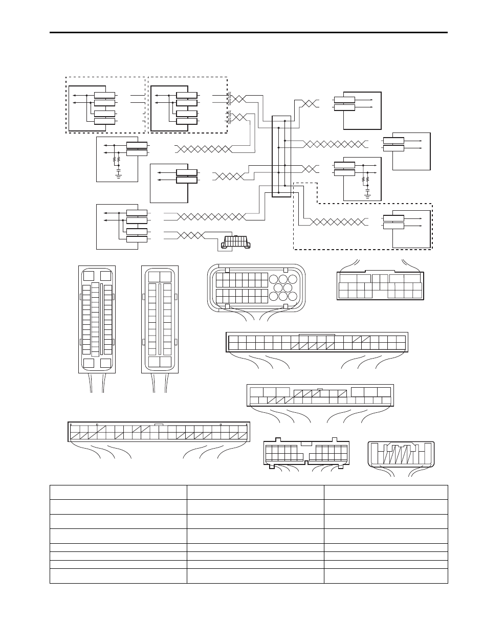
DTC U1073: Control Module Communication Bus Off
S6JB0B4504019
Wiring Diagram
WHT
RED
WHT
RED
WHT/BLU
WHT
RED
WHT
RED
E91-22
E91-23
E03-12
E03-6
E03-8
WHT/BLU
WHT/RED
E23-17
E23-9
G31-1
G31-3
G44-19
G44-18
WHT
RED
WHT
RED
E92-17
E92-7
G28-8
G28-10
G45-9
G45-10
WHT/RED
E03-10
WHT
RED
WHT
RED
2
WHT
RED
WHT/BLU
E53-13
E53-44
E53-46
WHT/RED
E53-42
1
3
4
5
10
6
8
7
9
G31-2
G31-4
11
[D]
E03
15
16
17
18
19
20
21
22
23
24
25
2
3
4
5
6
7
8
9
10
11
12
1
13
14
26
[I]
G44
1
2
3
4
5
6
7
8
9
10
11
14
15
16
36
34 33 32 31 30 29
24 23
37
18
19
20
[F]
6
5
16 15 14 13 12 11
4 3
24 23
21
22
10 9
8
7
2
1
19
20
18 17
E92
[J]
1
2
3
4
5
6
7
8
9
10
11
17
1615141312
2221201918
G28
[G]
G31
1
2
3
4
7
8
9
10
11
14
15
16
36
34
35
24 23
21
22
28 27
25
26
37
39 38
40
18 17
13 12
19
20
E91
1
2
3
10
11
12
16
17
18
15 14 13
19
20
21
25
26
5
6
[H]
[E]
17
18
19
20
21
22
23
24
25
26
27
28
29
30
31
33
34
35
36
37
38
39
40
32
1
2
3
4
5
6
7
8
9
10
11
12
13
14
15
16
E23
[C]
E53
16
1
15
2
3
4
5
6
7
8
9
10
11
12
13
14
17
18
19
20
21
22
23
24
25
26
27
28
29
30
31
32
33
34
35
36
37
38
39
40
41
42
43
44
45
46
47
[A]
[K]
G45
10 9
3 2 1
[A]
[B]
I6JB01450013-05
[A]: ESP
® model
[I]: Keyless start control module connector (viewed
from harness side)
6. 4WD control module (if equipped)
[B]: Non-ESP
® model
[J]: Combination meter connector (viewed from
harness side)
7. Keyless start control module (if equipped)
[C]: ESP
® control module connector (viewed from
terminal side)
[K]: Steering angle sensor connector (viewed from
harness side)
8. Combination meter
[D]: ABS control module connector (viewed from
terminal side)
1. ESP
® hydraulic unit / control module assembly
9. Steering angle sensor (if equipped)
[E]: ECM connector (viewed from harness side)
2. ABS hydraulic unit / control module assembly 10. Junction
connector
[F]: TCM connector (viewed from harness side)
3. ECM
11. Data link connector (DLC)
[G]: BCM connector (viewed from harness side)
4. TCM
[H]: 4WD control module connector (viewed from
harness side)
5. BCM

4E-31 ABS:
DTC Detecting Condition
Transmission error that is inconsistent between transmission data and transmission monitor (CAN bus monitor) data is
detected more than 7 times continuously.
DTC Troubleshooting
Step
Action
Yes
No
1
Was “ABS Check” performed?
Go to Step 2.
2
1) Check connection of connectors of all control modules
communicating by means of CAN.
2) Recheck DTC.
Is DTC U1073 indicated?
Go to Step 3.
Intermittent trouble.
Check for intermittent
referring to “Intermittent
and Poor Connection
Inspection in Section
00”.
3
1) Turn ignition switch to OFF position.
2) Disconnect connectors of all control modules
communicating by means of CAN.
3) Check CAN communication circuit between control
modules for open, short and high resistance.
Is each CAN communication circuit in good condition?
Go to Step 4.
Repair insulation of
CAN communication
line circuit referring to
“Precaution for CAN
Communication System
in Section 00”.
4
1) Connect connectors of disconnected control modules
communicating by means of CAN.
2) Disconnect each connector and check DTC for ABS in
turn.
• ECM
• TCM (A/T model)
• BCM
• 4WD control module (if equipped)
• Keyless start control module (if equipped)
• Combination meter
• Steering angle sensor (ESP
® model)
Is DTC U1073 detected?
Check ABS (ESP
®)
control module power
and ground circuit. If
circuits are OK,
substitute a known-
good ABS (ESP
®)
hydraulic unit / control
module assembly and
recheck.
Check applicable
control module power
and ground circuit. If
circuit is OK, substitute
a known-good
applicable control
module and recheck.

ABS: 4E-32
DTC U1100: Lost Communication with ECM (Reception Error)
S6JB0B4504020
Wiring Diagram
Refer to “DTC U1073: Control Module Communication Bus Off”.
DTC Detecting Condition
Reception error of communication data for ECM is detected more than specified time continuously.
DTC Troubleshooting
Step
Action
Yes
No
1
Was “ABS Check” performed?
Go to Step 2.
2
Check DTC for ABS.
Is DTC U1073 detected?
Go to “DTC U1073:
Control Module
Communication Bus
Off”.
Go to Step 3.
3
1) Check DTC for ECM.
Is DTC U0073 detected?
Go to “DTC U0073:
Control Module
Communication Bus Off
in Section 1A”.
Go to Step 4.
4
1) Check for proper connection at each ABS and ECM
terminals with ignition switch turned OFF.
2) If connections are OK, recheck ABS for DTC with engine
running.
Is there DTC U1100?
Go to Step 5.
Intermittent trouble.
Check for intermittent
referring to “Intermittent
and Poor Connection
Inspection in Section
00”.
5
1) Check connection of connectors of all control modules
communicating by means of CAN.
2) Check DTC for ABS.
Is DTC U1100 detected?
Go to Step 6.
Intermittent trouble.
Check for intermittent
referring to “Intermittent
and Poor Connection
Inspection in Section
00”.
6
1) Turn ignition switch to OFF position.
2) Disconnect connectors of ABS (ESP
®) control module
and ECM.
3) Check CAN communication circuit between ABS and
ECM for open, short and high resistance.
Is CAN communication circuit in good condition?
Go to Step 7.
Repair insulation of
CAN communication
line circuit referring to
“Precaution for CAN
Communication System
in Section 00”.
7
1) Disconnect connectors of all control modules
communicating by means of CAN.
2) Check CAN communication circuit between control
modules other than Step 6 for open, short and high
resistance.
Is each CAN communication circuit in good condition?
Go to Step 8.
Repair or replace the
CAN communication
line.
8
1) Connect connectors of disconnected control modules
communicating by means of CAN.
2) Disconnect each connector and check DTC for ABS in
turn.
• ECM
• TCM (A/T model)
• BCM
• 4WD control module (if equipped)
• Keyless start control module (if equipped)
• Combination meter
• Steering angle sensor (ESP
® model)
Is DTC U1073 detected?
Check ABS (ESP
®)
control module power
and ground circuit. If
circuits are OK,
substitute a known-
good ABS (ESP
®)
hydraulic unit / control
module assembly and
recheck.
Check applicable
control module power
and ground circuit. If
circuit is OK, substitute
a known-good
applicable control
module and recheck.
Нет комментариевНе стесняйтесь поделиться с нами вашим ценным мнением.
Текст