Suzuki Grand Vitara JB627. Manual — part 174
4A-15 Brake Control System and Diagnosis:
4) Connect reservoir lead wire at coupler.
5) Fill reservoir with specified fluid.
6) After installing, bleed air from brake system referring
to “Air Bleeding of Brake System” and at the same
time bleed air from clutch system referring to “Air
Bleeding of Clutch System in Section 5C” (M/T
model).
7) Upon completion of installation, check for fluid
leakage.
Master Cylinder Assembly Removal and
Installation
S6JB0B4106015
CAUTION
!
• Never disassemble master cylinder.
Disassembly will spoil its original function.
If faulty condition is found, replace it with
new one as an assembly.
• Do not allow brake fluid to get on painted
surfaces. Painted surfaces will be
damaged by brake fluid, flush it with water
immediately if any fluid is spilled.
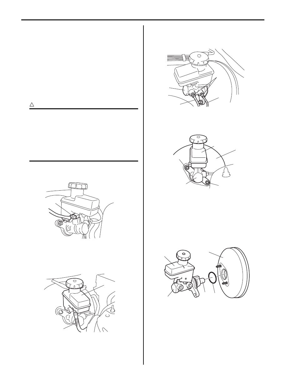
Removal
1) Disconnect reservoir lead wire at coupler (1).
2) Clean outside of master cylinder and take out fluid
with syringe or such.
3) Disconnect clutch reservoir hose (1) from reservoir
(2) (M/T model).
4) Loosen brake pipe flare nuts (2) for master cylinder
(1).
5) Disconnect brake pipes (3) from master cylinder (1).
6) Loosen master cylinder fixing nuts (1) and then
remove master cylinder (2) with reservoir (3) from
brake booster (4).
Installation
1) Install new master cylinder O-ring (1) to master
cylinder.
2) Apply grease to piston rod “A”. Use specified grease
to spare parts.
3) Install master cylinder (2) with reservoir (3) to brake
booster (4).
1
I5JB0A410016-02
2
1
I5JB0A410012-02
2
3
3
1
I5JB0A410017-01
1
2
1
3
4
I5JB0A410018-02
1
2
3
4
“A”
I6JB0B410003-01

Brake Control System and Diagnosis: 4A-16
4) Tighten master cylinder fixing nuts (1) to specified
torque.
Tightening torque
Master cylinder fixing nut (a): 18 N·m (1.8 kgf-
m, 13.0 lb-ft)
5) Connect brake pipes to master cylinder and tighten
brake pipe flare nuts (1) to specified torque.
Tightening torque
Brake pipe flare nut (M10) (a): 16 N·m (1.6 kgf-
m, 12.0 lb-ft)
Brake pipe flare nut (M12) (a): 19 N·m (1.9 kgf-
m, 14.0 lb-ft)
6) Connect clutch reservoir hose (1) to reservoir (2) (M/
T model).
7) Connect reservoir lead wire at coupler.
8) Fill reservoir with specified brake fluid.
9) After installing, bleed air from brake system referring
to “Air Bleeding of Brake System” and at the same
time bleed air from clutch system referring to “Air
Bleeding of Clutch System in Section 5C” (M/T
model).
10) Perform brake test and check each installed part for
fluid leakage.
Master Cylinder Assembly Inspection
S6JB0B4106016
• Check master cylinder for corrosion and smooth
operation.
• Inspect distance “a” to be the following.
If measurement is out of specification, replace master
cylinder assembly.
Distance
“a”: 72.0 mm (2.83 in.) or more
1,(a)
1,(a)
I5JB0A410021-02
1,(a)
I5JB0A410020-01
2
1
I5JB0A410012-02
I5JB0A410022-01
4A-17 Brake Control System and Diagnosis:
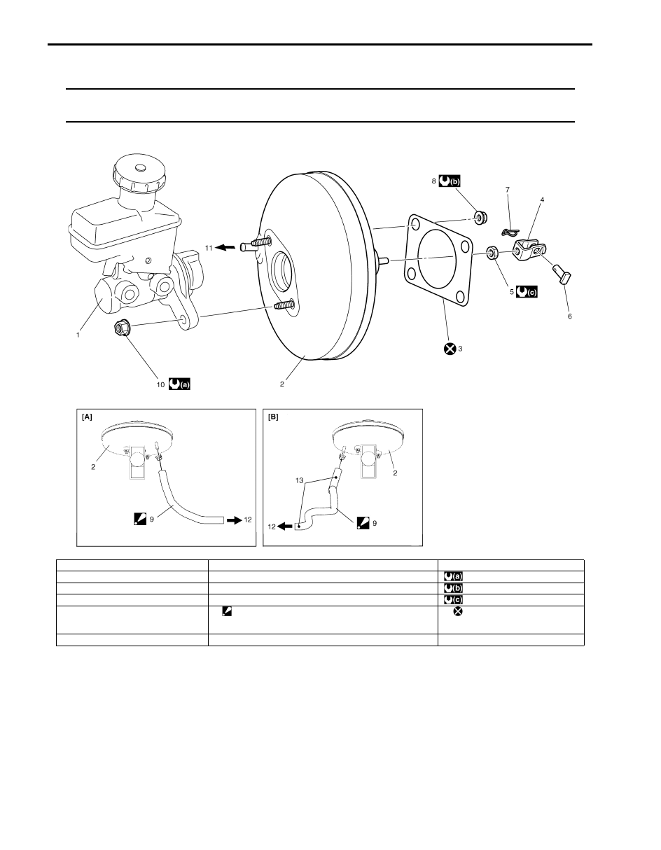
Brake Booster Components
S6JB0B4106017
NOTE
The difference between RH steering vehicle and LH steering vehicle booster components is the
location of vacuum hose.
I6JB0B410001-02
[A]: RHD model
5. Clevis pin lock nut
11. To vacuum hose
[B]: LHD model
6. Clevis pin
: 18 N
⋅m (1.8 kgf-m, 13.0 lb-ft)
1. Brake master cylinder assembly
7. Clip
: 13 N
⋅m (1.3 kgf-m, 9.5 lb-ft)
2. Brake booster assembly
8. Booster attaching nut
: 26 N
⋅m (2.6 kgf-m, 19.0 lb-ft)
3. Gasket
9. Brake vacuum hose
: Be sure to direct arrow mark to engine side (12) and
location mark (13) to up side.
: Do not reuse.
4. Push rod clevis
10. Master cylinder fixing nut
Brake Control System and Diagnosis: 4A-18
Brake Booster Removal and Installation
S6JB0B4106018
CAUTION
!
Never disassemble brake booster.
Disassembly will spoil its original function. If
is found faulty, replace it with new one.
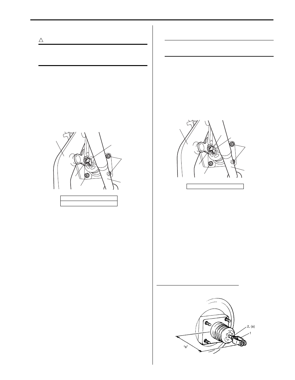
Removal
1) Disconnect brake pipes from ABS (ESP
®) actuator.
2) Remove master cylinder assembly, referring to
“Master Cylinder Assembly Removal and
Installation”.
3) Disconnect brake vacuum hose from brake booster.
4) Remove clip (2) and the disconnect clevis pin (3).
5) Remove attaching nuts (1) and then remove booster
as shown in the figure.
Installation
NOTE
• Check length of push rod clevis (2). Refer
to “Booster Push Rod Clevis Adjustment”.
1) Install gasket to booster and then install booster to
dash panel as shown in the figure. Then connect
booster push rod clevis (2) to pedal arm (3) with
clevis pin inserting from left (4) and clip (5).
2) Tighten booster attaching nuts (6) to the specified
torque.
Tightening torque
Booster attaching nut (a): 13 N·m (1.3 kgf-m, 9.5
lb-ft)
3) Connect brake vacuum hose to brake booster
referring to “Brake Booster Components”.
4) Install master cylinder referring to “Master Cylinder
Assembly Removal and Installation”.
5) After installing, fill reservoir with specified brake fluid
and bleed brake system. Check each installed part
for fluid leakage and perform brake test.
Booster Push Rod Clevis Adjustment
S6JB0B4106019
Install push rod clevis (1) so that measurement “a” is
obtained and torque nut (2) to specification.
Tightening torque
Clevis pin lock nut (a): 26 N·m (2.6 kgf-m, 19.0 lb-ft)
Clevis installing position (length “a”)
“a”: 133.5 – 134.5 mm (5.26 – 5.30 in.)
4. Steering column
5. Brake pedal arm
5
2
1
4
3
1
I5JB0A410024-01
1. Steering column
3
5
6,(a)
1
4
6,(a)
2
I5JB0A410025-01
IYSQ01410050-01
Нет комментариевНе стесняйтесь поделиться с нами вашим ценным мнением.
Текст