Suzuki Grand Vitara JB627. Manual — part 173
4A-11 Brake Control System and Diagnosis:
Booster Operation Check
S6JB0B4106010
There are two ways to perform this inspection, with and
without a tester. Ordinarily, it is possible to roughly
determine its condition without using a tester.
NOTE
For this check, make sure that no air is in
hydraulic line.
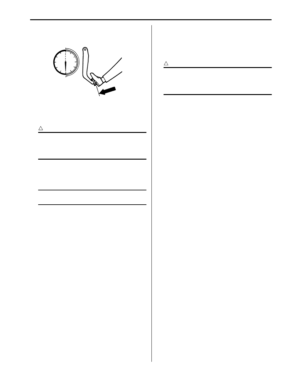
Inspection without Tester
Check air tightness
1) Start engine.
2) Stop engine after running for 1 to 2 minutes.
3) Depress brake pedal several times with the same
load as in ordinary braking and observe pedal travel.
If pedal goes down deep the first time but its travel
decreases as it is depressed the second and more
times, air tightness is obtained.
4) If pedal travel doesn’t change, air tightness isn’t
obtained.
NOTE
If defective, inspect vacuum lines and sealing
parts, and replace any faulty part.
When this has been done, repeat the entire
test.
Check operation
1) With engine stopped, depress brake pedal several
times with the same load and make sure that pedal
travel doesn’t change.
2) Start engine while depressing brake pedal. If pedal
travel increases a little, operation is satisfactory. But
no change in pedal travel indicates malfunction.
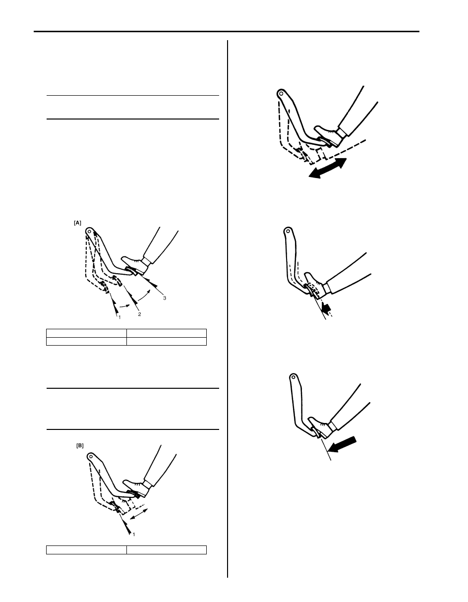
Check air tightness under load
1) With engine running, depress brake pedal. Then
stop engine while holding brake pedal depressed.
[A]: Good
2. 2nd
1. 1st
3. 3rd
[B]: No Good
1. 1st, 2nd, 3rd
I5JB0A410008-01
I5JB0A410009-01
IYSQ01410018-01
IYSQ01410019-01
IYSQ01410020-01
Brake Control System and Diagnosis: 4A-12
2) Hold brake pedal depressed for 30 seconds. If pedal
height does not change, condition is good. But it isn’t
if pedal rises.
Front Brake Hose / Pipe Removal and
Installation
S6JB0B4106011
CAUTION
!
Do not allow brake fluid to get on painted
surfaces. Painted surfaces will be damaged
by brake fluid, flush it with water immediately
if any fluid is spilled.
Removal
1) Raise and support vehicle properly. Remove tire and
wheel.
NOTE
This operation is not necessary when
removing pipes connecting master cylinder.
2) Clean dirt and foreign material from both flexible
hose end and pipe end fittings.
3) Drain brake fluid in reservoir.
4) Remove brake flexible hose or pipe.
Installation
Reverse brake flexible hose removal procedure, noting
the following.
• Tighten brake pipe flare nut to specified torque.
Tightening torque
Brake pipe flare nut (M10): 16 N·m (1.6 kgf-m,
12.0 lb-ft)
Brake pipe flare nut (M12): 19 N·m (1.9 kgf-m,
14.0 lb-ft)
• Make sure that steering wheel is in straight-forward
position and flexible hose has not twist or kink.
• Check to make sure that flexible hose doesn’t contact
any part of suspension, both in extreme right and
extreme left turn conditions.
If it does at any point, remove and correct. Fill and
maintain brake fluid level in reservoir.
• Bleed brake system. Refer to “Air Bleeding of Brake
• Perform brake test and check installed part for fluid
leakage.
Rear Brake Hose / Pipe Removal and
Installation
S6JB0B4106012
CAUTION
!
Do not allow brake fluid to get on painted
surfaces. Painted surfaces will be damaged
by brake fluid, flush it with water immediately
if any fluid is spilled.
Removal
1) Raise and support vehicle properly. Remove tire and
wheel.
2) Clean dirt and foreign material from both flexible
hose end and pipe end fittings.
3) Drain brake fluid in reservoir.
4) Remove brake flexible hose or pipe.
Installation
Reverse brake flexible hose removal procedure, noting
the following.
• Fill and maintain brake fluid level in reservoir.
• Bleed brake system. Refer to “Air Bleeding of Brake
• Perform brake test and check each installed part for
fluid leakage.
• Install clamps properly referring to the figure and
tighten bolts.
• When installing hose, make sure that it has no twist or
kink.
IYSQ01410021-01
4A-13 Brake Control System and Diagnosis:
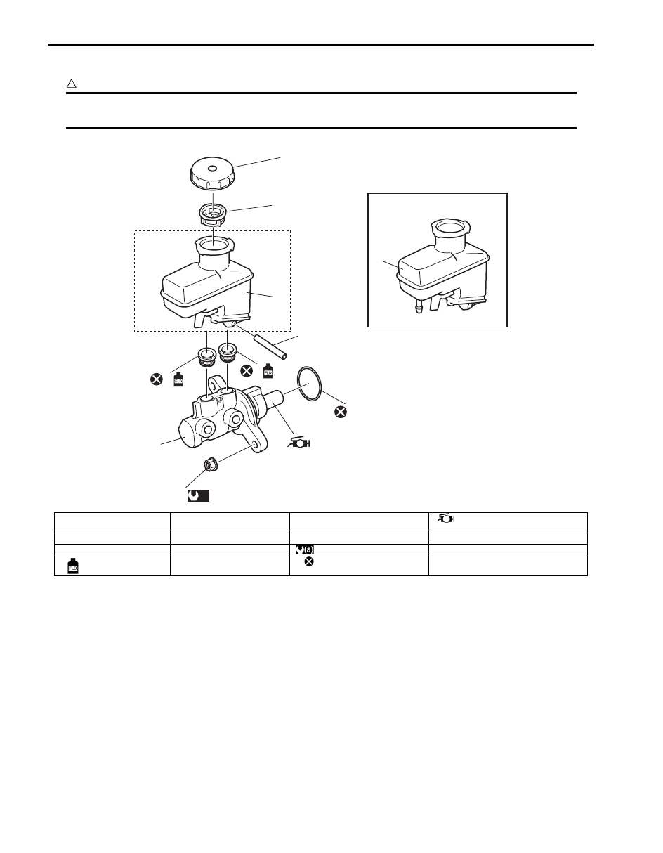
Master Cylinder Components
S6JB0B4106013
CAUTION
!
Never disassemble master cylinder. Disassembly will spoil its original function. If faulty condition is
found, replace it with new one as an assembly.
[A]
[B]
4
5
3
3
2
2
1
7
6
8
(a)
I6JB0B410002-01
[A]: A/T model
3. Reservoir
7. O-ring
: Apply grease to piston rod
(Grease included in spare parts)
[B]: M/T model
4. Reservoir cap
8. Master cylinder fixing nut
1. Master cylinder body
5. Filter
: 18 N
⋅m (1.8 kgf-m, 13.0 lb-ft)
2. Grommet
: Apply brake fluid.
6. Reservoir connector pin
: Do not reuse.
Brake Control System and Diagnosis: 4A-14
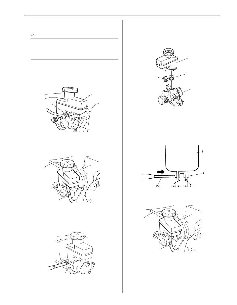
Master Cylinder Reservoir Removal and
Installation
S6JB0B4106014
CAUTION
!
Do not allow brake fluid to get on painted
surfaces. Painted surfaces will be damaged
by brake fluid, flush it with water immediately
if any fluid is spilled.
Removal
1) Disconnect reservoir lead wire at coupler (1).
2) Clean outside of reservoir (2) and master cylinder
(3).
3) Take out fluid with syringe or such.
4) Disconnect clutch reservoir hose (1) from reservoir
(2) (M/T model).
5) Remove reservoir connector pin (1) by using special
tool and then reservoir.
Special tool
(A): 09916–44310
Installation
1) When using new grommets (3), lubricate them with
the same fluid as the one to fill reservoir (1) with.
Then press-fit grommets (3) to master cylinder (2).
Grommets (3) must be seated in place.
2) Install reservoir (1) and drive in reservoir connector
pin (2) by using special tool (A). till both of its ends at
the right and left of reservoir becomes the same
length.
Special tool
(A): 09916–44310
3) Connect clutch reservoir hose (1) to reservoir (2) (M/
T model).
3
2
1
I5JB0A410011-02
2
1
I5JB0A410012-02
1
(A)
I5JB0A410013-02
1
2
3
3
I5JB0A410014-01
I5JB0A410015-01
2
1
I5JB0A410012-02
Нет комментариевНе стесняйтесь поделиться с нами вашим ценным мнением.
Текст