Suzuki Grand Vitara JB627. Manual — part 210

5A-24 Automatic Transmission/Transaxle:
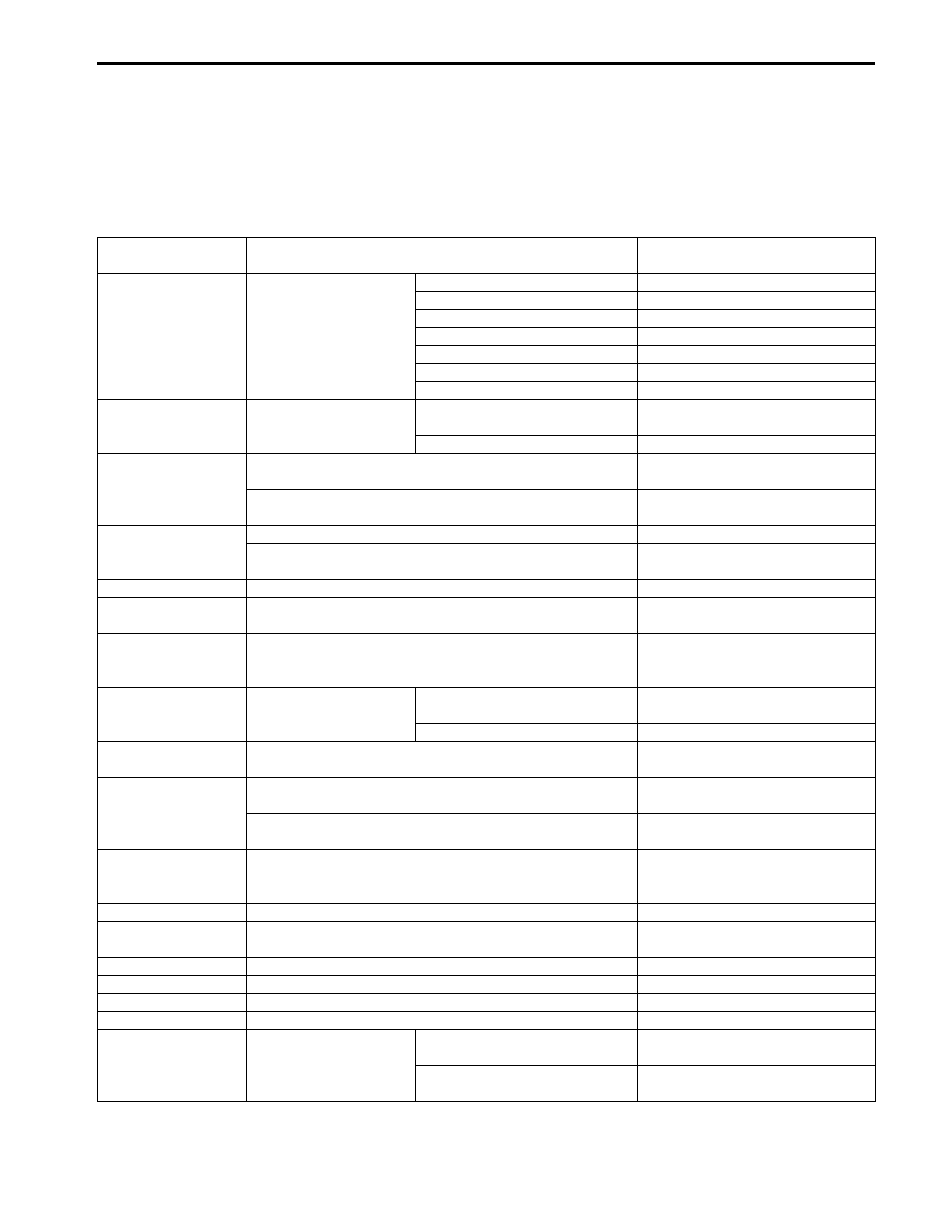
P1702
Internal Control Module Memory Check
Sum Error
• Power supply for all solenoid valves is cut.
• Gear position is fixed according to select lever position
as shown in the following.
R: Reverse
D: 4th
3: 3rd
L: 3rd
P1703
CAN Invalid Data-TCM
In case of accelerator pedal and/or throttle position signal
malfunction:
• Accelerator pedal and/or throttle opening used for line
pressure control is assumed to be 100%.
• Accelerator pedal and/or throttle opening used for gear
shifting control is assumed to be 0%.
• Upshifting to 5th gear is inhibited.
• Lock-up function is inhibited to operate.
• Line pressure control at gear shifting is inhibited.
• Slope shift control is inhibited.
In case of engine coolant temperature signal malfunction:
• Engine coolant temperature is assumed to be warming
up condition.
• Slope shift control is inhibited.
In case of engine revolution signal malfunction:
• Engine revolution is assumed to be max value.
• Lock-up function is inhibited to operate.
• Slope shift control is inhibited.
• Learning control is inhibited.
In case of engine torque signal malfunction:
• Engine torque is assumed to be max value.
• Slope shift control is inhibited.
In case of vehicle speed signal.
• Slope shift control is inhibited.
P1723
Range Select Switch Malfunction
• 4 position switch signal is invalidity.
P0073
Control Module Communication Bus Off
• Throttle opening used for line pressure control is
assumed to be 100%.
• Throttle opening used for gear shifting control is
assumed to be 0%.
• Engine revolution is assumed to be max value.
• Engine torque is assumed to be max value.
• Engine coolant temperature is assumed to be warming
up condition.
• Lock-up function is inhibited to operate.
• Upshifting to 5th gear is inhibited.
• Slope shift control is inhibited.
U0100
Lost Communication With ECM
U0140
Lost Communication With Body Control
Module
• Power mode is inhibited.
P2763
Torque Converter Clutch Circuit High
• Power supply for TCC solenoid is cut.
• Learning control is inhibited.
• Vehicle starting at 2nd gear is inhibited.
P2764
Torque Converter Clutch Circuit Low
DTC No.
Trouble Area
Fail Safe Operation
Automatic Transmission/Transaxle: 5A-25
Scan Tool Data
S6JB0B5104007
As the data values given in the following table are standard values estimated on the basis of values obtained from the
normally operating vehicles by using a scan tool, use them as reference value. Even when the vehicle is in good
condition, there may be cases where the checked value does not fall within each specified data range. Therefore,
judgment as abnormal should not be made by checking with these data alone.
Also, condition in the following table that can be checked by the scan tool are those detected by TCM and output from
TCM as commands and there may be cases where the automatic transmission or actuator is not operating (in the
condition) as indicated by the scan tool.
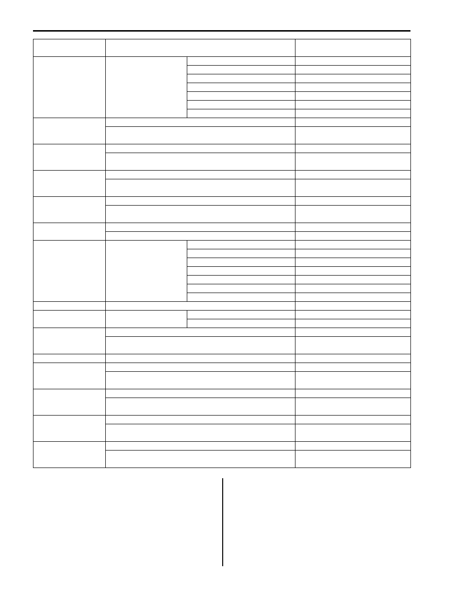
Scan Tool Data
Vehicle Condition
Normal Condition / Reference
Values
Gear Position
Ignition switch ON
POWER mode OFF
Select lever is in “P” position
P/N
Select lever is in “R” position
R
Select lever is in “N” position
P/N
Select lever is in “D” position
1st
Select lever is in “4” position
1st
Select lever is in “3” position
1st
Select lever is in “L” position
1st
Throttle Position
Ignition switch ON
Accelerator pedal is depressed
0 – 100% (varies depending on
depressed value)
Accelerator pedal is released
0 – 5%
Input Shaft Rev
At engine idle speed and selector lever is in “P” position
(Engine idle speed is displayed in
increments of 50 rpm)
At 60 km/h (37.5 mile/h) constant speed, 20% or less
throttle opening and 4th gear
2300 RPM
(displayed in increments of 50 rpm)
Output Shaft Rev
At vehicle stop
0 RPM
At 60 km/h (37.5 mile/h) constant speed, 20% or less
throttle opening and 4th gear
2300 RPM
(displayed in increments of 50 rpm)
Vehicle Speed 1
At vehicle stop
0 km/h, 0 MPH
Battery Voltage
Ignition switch ON and engine stop
Battery voltage is displayed (8 – 16
V)
ATF Temp
After driving at 60 km/h (37.5 mile/h) for 15 minutes or
more, and A/T fluid temperature around sensor reaches 70
– 80
°C (158 – 176 °F)
70 – 80
°C (158 – 176 °F)
Accel Effective Pos
Ignition switch ON
Accelerator pedal is depressed
0 – 100% (varies depending on
depressed value)
Accelerator pedal is released
0%
Press Cont Sol
At vehicle stop, closed throttle, engine idle speed and 1st
gear
9.5%
Slip RPM
Engine running at idle speed and selector lever is in “P”
range
0
± 25 RPM
Engine running, vehicle stop and selector lever is in “D”
range
Engine speed is displayed
ATF Temp 2
After driving at 60 km/h (37.5 mile/h) for 15 minutes or
more, and A/T fluid temperature around sensor reaches 70
– 80
°C (158 – 176 °F)
70 – 80
°C (158 – 176 °F)
Engine Speed
At engine idle speed
Engine idle speed is displayed
Coolant Temp
Ignition switch ON
Engine coolant temperature is
displayed
Target Engine Torque Ignition switch ON
0 N
⋅m
Engine Torque
Ignition switch ON
0 N
⋅m
MIL request
Ignition switch ON
OFF
Fuel Cut Flag
Ignition switch ON
OFF
O/D Off Switch
Ignition switch ON
Shift selector lever to other
below range
ON
Shift selector lever to “P”, “N”
and “D” range
OFF
5A-26 Automatic Transmission/Transaxle:
Scan Tool Data Definitions
Gear Position (1
ST
, 2
ND
, 3
RD
, 4
TH
, 5
TH
, N, R): This
parameter is indicated actual gear position.
Throttle Position (%): It indicates throttle valve
opening ratio sent from ECM through CAN
communication line.
Input Shaft Rev (RMP): It indicates input shaft
revolution computed by reference pulses coming
from input shaft speed sensor on transmission case.
Output Shaft Rev (RMP): It indicates output shaft
revolution computed by reference pulses coming
from output shaft speed sensor on transmission
case.
Vehicle Speed 1 (Km/h): This parameter is competed
by output shaft speed sensor and 4L/N switch on
TCM. Gear shift schedule relate this parameter.
Battery Voltage (V): It indicates battery voltage read by
TCM as analog input signal by TCM.
Trans Range
Ignition switch ON
Select lever is in “P” position
P
Select lever is in “R” position
R
Select lever is in “N” position
N
Select lever is in “D” position
D
Select lever is in “4” position
D
Select lever is in “3” position
3
Select lever is in “L” position
L
Shift Sol A Con
At vehicle stop, closed throttle and 1st gear
ON
At 30 km/h (18.5 mile/h) constant speed, 20% or less
throttle opening and 3rd gear
OFF
Shift Sol A Mon
At vehicle stop, closed throttle and 1st gear
ON
At 30 km/h (18.5 mile/h) constant speed, 20% or less
throttle opening and 3rd gear
OFF
Shift Sol B Con
At vehicle stop, closed throttle and 1st gear
OFF
At 20 km/h (12.5 mile/h) constant speed, 20% or less
throttle opening and 2nd gear
ON
Shift Sol B Mon
At vehicle stop, closed throttle and 1st gear
OFF
At 20 km/h (12.5 mile/h) constant speed, 20% or less
throttle opening and 2nd gear
ON
4WD Low Switch
Ignition switch ON, transfer position switch is “4H”
OFF
Ignition switch ON, transfer position switch is “4L”
ON
D Range Signal
Ignition switch ON
Select lever is in “P” position
P/N range
Select lever is in “R” position
D range
Select lever is in “N” position
P/N range
Select lever is in “D” position
D range
Select lever is in “4” position
D range
Select lever is in “3” position
D range
Select lever is in “L” position
D range
A/C switch
Ignition switch ON and air conditioner switch OFF
Cancel
Brake Switch
Ignition switch ON
Brake pedal is depressed
ON
Brake pedal is released
OFF
TCC Sol Duty
At vehicle stop, closed throttle and 1st gear
0%
At 80 km/h (50 mile/h) constant speed, 30% or less throttle
opening and 4th gear. (“4” range)
100%
Vehicle Speed 2
At vehicle stop
0 km/h, 0 MPH
Press cont sol B
At vehicle stop, closed throttle and 1st gear
0%
At 80 km/h (50 mile/h) constant speed, 30% or less throttle
opening and 5th gear
100%
Press cont sol C
At vehicle stop, closed throttle and 1st gear
100%
At 80 km/h (50 mile/h) constant speed, 30% or less throttle
opening and 5th gear
0%
Shift Sol E Con
At vehicle stop, closed throttle and 1st gear
OFF
At 80 km/h (50 mile/h) constant speed, 30% or less throttle
opening and 5th gear
ON
Shift Sol E Mon
At vehicle stop, closed throttle and 1st gear
OFF
At 80 km/h (50 mile/h) constant speed, 30% or less throttle
opening and 5th gear
ON
Scan Tool Data
Vehicle Condition
Normal Condition / Reference
Values

Automatic Transmission/Transaxle: 5A-27
ATF Temp (
°C): It indicates ATF temperature detected
by signal from transmission fluid temperature
sensor-A installed in valve body.
Accel Effective Pos (%): It indicates accelerator pedal
opening ratio detected by signal through CAN
communication line fed from ECM.
Press Cont Sol (%): Electric current value ratio
between electric current value being outputted from
TCM to pressure control solenoid-A and maximum
value can be outputted by TCM.
Slip RPM (RMP): This parameter indicates slipping
rotation in the torque converter (difference between
input shaft rotation and engine rotation)
ATF Temp 2 (
°C): It indicates ATF temperature
detected by signal from transmission fluid
temperature sensor-B installed in valve body.
Engine Speed (RPM): It indicates engine speed
computed by signal through CAN communication
line fed from ECM.
Coolant Temp (
°C): It indicates engine coolant
temperature detected by signal through CAN
communication line fed from ECM.
Target Engine Torque (Nm): It indicates target engine
torque detected by signal through CAN
communication line fed from ECM.
Engine Torque (Nm): It indicates actual engine torque
detected by signal through CAN communication line
fed from ECM.
MIL Request (ON, OFF): ON: Signal which TCM
requires combination meter to turn ON malfunction
indicator lamp.
OFF: Signal which TCM does not require
combination meter to turn ON malfunction indicator
lamp.
Fuel Cut Flag: ON: Signal which inform that fuel cut is
operating.
OFF: Signal which inform that fuel cut is not
operating.
O/D Off Switch (ON, OFF): Inputted signal from “4”
position switch in select lever assembly.
ON: Shift selector lever to other below range.
OFF: Shift selector lever to P, N and D range.
Trans Range (P, R, N, D, 3, L): It indicates
transmission range according to transmission range
switch signal.
Shift Sol A Con / MON (ON, OFF): COM-ON: ON
command being outputted to shift solenoid-A.
COM-OFF: OFF command not being outputted to
shift solenoid-A.
MON-ON: Electricity being passed to shift solenoid-
A.
MON-OFF: Electricity not being passed to shift
solenoid-A.
Shift Sol B Con / MON (ON, OFF): COM-ON: ON
command being outputted to shift solenoid-B.
COM-OFF: OFF command not being outputted to
shift solenoid-B.
MON-ON: Electricity being passed to shift solenoid-
B.
MON-OFF: Electricity not being passed to shift
solenoid-B.
4WD Low Switch (ON, OFF): Inputted signal from
4WD low switch on transfer case.
ON: Transfer gear position is 4L
OFF: Transfer gear position is 4H
D RANGE SIGNAL (P/N range, D range): ON: Signal
which TCM require ECM to increase idle speed
OFF: Signal which TCM does not require ECM to
increase idle speed
A/C Switch (ON, OFF): ON: Signal which inform that
air conditioner compressor is turned ON.
OFF: Signal which inform that air conditioner
compressor is turned OFF.
Brake Switch (ON, OFF): Brake light switch position
detected by signal through CAN communication line
fed from ECM.
ON: Brake pedal depressed
OFF: Brake pedal released
TCC Sol Duty (%): Electric current value ration
between electric current value being outputted from
TCM to TCC solenoid and maximum value can be
outputted by TCM.
Vehicle Speed 2 (Km/h): It indicates actual vehicle
speed detected by signal through CAN
communication line fed from ECM.
Press Cont Sol B (%): Electric current value ratio
between electric current value being outputted from
TCM to pressure control solenoid-B and maximum
value can be outputted by TCM.
Press Cont Sol C (%): Electric current value ratio
between electric current value being outputted from
TCM to pressure control solenoid-C and maximum
value can be outputted by TCM.
Shift Sol E Con / MON (ON, OFF): COM-ON: ON
command being outputted to shift solenoid-E.
COM-OFF: OFF command not being outputted to
shift solenoid-E.
MON-ON: Electricity being passed to shift solenoid-
E.
MON-OFF: Electricity not being passed to shift
solenoid-E.
Нет комментариевНе стесняйтесь поделиться с нами вашим ценным мнением.
Текст