Suzuki Grand Vitara JB627. Manual — part 209

5A-20 Automatic Transmission/Transaxle:
1-2 Shift
The gear commanded by TCM
does not match the actual gear
when driving.
2 driving cycles 2 driving cycles *2
Pressure Control Solenoid “C”
Stuck On
The gear commanded by TCM
does not match the actual gear
when driving.
2 driving cycles 2 driving cycles *2
Pressure Control Solenoid “A”
Control Circuit Low
No electric flow is detected on
pressure control solenoid circuit.
1 driving cycle
1 driving cycle
Pressure Control Solenoid “A”
Control Circuit High
Too much electric flow is
detected on pressure control
solenoid circuit.
1 driving cycle
1 driving cycle
Pressure Control Solenoid “B”
Control Circuit Low
No electric flow is detected on
pressure control solenoid circuit.
1 driving cycle
1 driving cycle
Pressure Control Solenoid “B”
Control Circuit High
Too much electric flow is
detected on pressure control
solenoid circuit.
1 driving cycle
1 driving cycle
Pressure Control Solenoid “C”
Control Circuit Low
No electric flow is detected on
pressure control solenoid circuit.
1 driving cycle
1 driving cycle
Pressure Control Solenoid “C”
Control Circuit High
Too much electric flow is
detected on pressure control
solenoid circuit.
1 driving cycle
1 driving cycle
Shift Solenoid “A” Control
Circuit Low
Voltage of shift solenoid terminal
is low although TCM is
commanding shift solenoid to
turn ON.
1 driving cycle
1 driving cycle
Shift Solenoid “A” Control
Circuit High
Voltage of shift solenoid terminal
is high although TCM is
commanding shift solenoid to
turn OFF.
1 driving cycle
1 driving cycle
Shift Solenoid “B” Control
Circuit Low
Voltage of shift solenoid terminal
is low although TCM is
commanding shift solenoid to
turn ON.
1 driving cycle
1 driving cycle
Shift Solenoid “B” Control
Circuit High
Voltage of shift solenoid terminal
is high although TCM is
commanding shift solenoid to
turn OFF.
1 driving cycle
1 driving cycle
Shift Solenoid “E” Control
Circuit Low
Voltage of shift solenoid terminal
is low although TCM is
commanding shift solenoid to
turn ON.
1 driving cycle
1 driving cycle
Shift Solenoid “E” Control
Circuit High
Voltage of shift solenoid terminal
is high although TCM is
commanding shift solenoid to
turn OFF.
1 driving cycle
1 driving cycle
Internal Control Module
Memory Check Sum Error
Calculation of current data
stored in TCM is not correct
comparing with pre-stored
checking data in TCM.
1 driving cycle
1 driving cycle
CAN Invalid Data - TCM
TCM receives malfunction signal
of throttle position, engine
coolant temperature, engine
revolution and engine torque
from ECM.
1 driving cycle
1 driving cycle *2
Range Select Switch
Malfunction
4 position switch signal is
inputted out of specified value.
1 driving cycle *1 1 driving cycle *2
DTC No.
Detecting Item
Detecting Condition
(DTC will set when detecting)
Driving Cycle
A
B

Automatic Transmission/Transaxle: 5A-21
NOTE
*1: TCM does not output MIL ON signal to combination meter but DTC is stored in TCM.
*2: TCM does not output transmission warning light ON signal to combination meter but DTC is stored
in TCM.
4WD Low switch circuit
malfunction (Short)
Actual transfer position is 2H or
4H although transfer low signal
is inputted.
1 driving cycle
1 driving cycle *2
4WD Low switch circuit
malfunction (Open)
Actual transfer position is 4L
although transfer low signal is
not inputted.
1 driving cycle
1 driving cycle *2
Transmission Fluid
Temperature Sensor “B” Circuit
Low
Sensor output voltage is too low.
1 driving cycle
1 driving cycle
Transmission Fluid
Temperature Sensor “B” Circuit
High
Sensor output voltage is too
high.
1 driving cycle
1 driving cycle
Torque Converter Clutch Circuit
High
Too much electric flow is
detected on TCC solenoid
circuit.
1 driving cycle
1 driving cycle
Torque Converter Clutch Circuit
Low
No electric flow is detected on
TCC solenoid circuit.
1 driving cycle
1 driving cycle
U0073
Control Module
Communication Bus Off
Transmitting error detected to
TCM for specified time
continuously.
1 driving cycle
1 driving cycle
U0100
Lost Communication With ECM Receiving error from ECM
detected to TCM for specified
time continuously.
1 driving cycle
1 driving cycle
U0140
Lost Communication With Body
Control Module
Receiving error from BCM
detected to TCM for specified
time continuously.
1 driving cycle *1 1 driving cycle *2
DTC No.
Detecting Item
Detecting Condition
(DTC will set when detecting)
Driving Cycle
A
B
5A-22 Automatic Transmission/Transaxle:
DTC Check
S6JB0B5104004
NOTE
The MIL is turned on when the ECM and/or
TCM detect malfunction(s). Each ECU stores
diagnostic information as the diagnostic
trouble code (DTC) in its memory and outputs
the DTC to the scan tool. Therefore, check
both of the ECUs for any DTC with the scan
tool because the DTC stored in ECU and TCM
is not read and displayed at a time. However,
each of the ECUs needs not to be checked
with the generic scan tool because the DTC
stored in ECM and TCM is read and displayed
at a time.
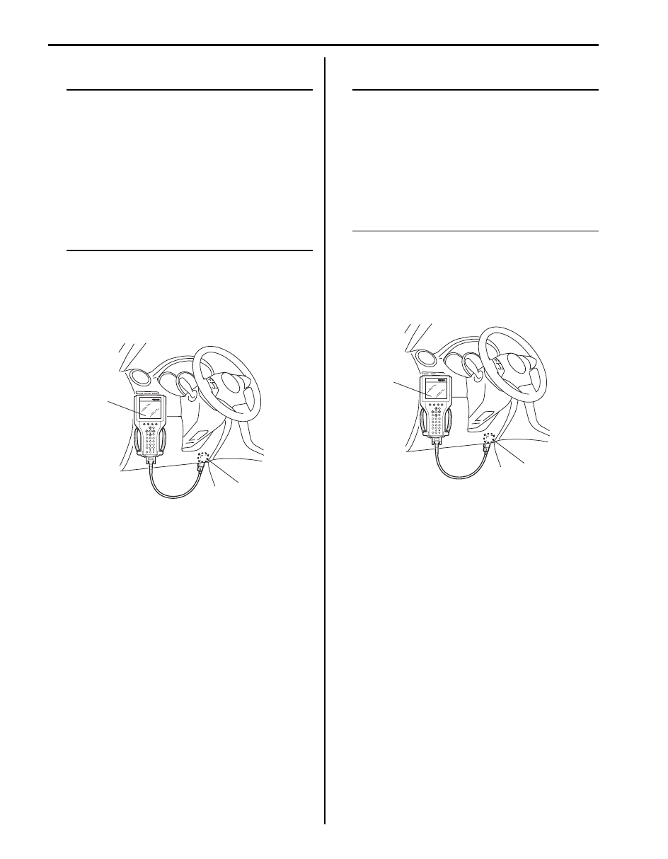
1) Turn ignition switch OFF.
2) Connect SUZUKI scan tool to data link connector
(DLC).
Special tool
(A): SUZUKI scan tool
3) Read DTC according to instructions displayed on
SUZUKI scan tool and write it down. Refer to
SUZUKI scan tool operator’s manual for further
details.
4) After completing the check, turn ignition switch OFF
and disconnect SUZUKI scan tool from data link
connector (DLC).
DTC Clearance
S6JB0B5104005
NOTE
DTC and freeze frame data stored in TCM
memory are also cleared in following cases.
Be careful not to clear them before keeping
their record.
• When power to TCM is cut off (by
disconnecting battery cable, removing
fuse or disconnecting TCM connector).
• When the same malfunction (DTC) is not
detected again during 40 engine warm-up
cycles.
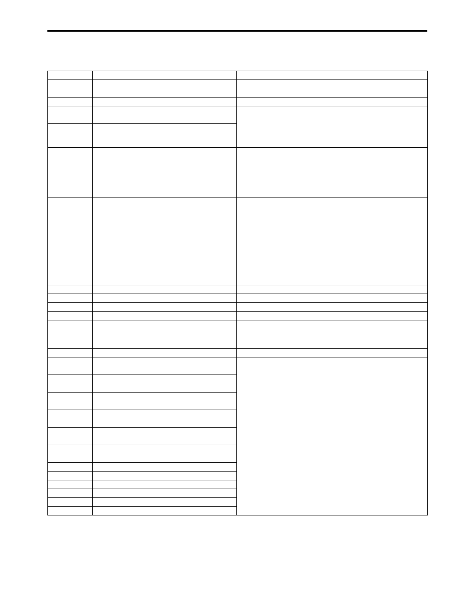
1) Turn ignition switch OFF.
2) Connect SUZUKI scan tool to data link connector
(DLC) (1).
Special tool
(A): SUZUKI scan tool
3) Clear DTC according to instructions displayed on
SUZUKI scan tool. Refer to SUZUKI scan tool
operator’s manual for further details.
4) Clear DTC according to instructions displayed on
SUZUKI scan tool. Refer to SUZUKI scan tool
operator’s manual for further details.
(A)
1
I5JB0A510016-01
(A)
1
I5JB0A510016-01
Automatic Transmission/Transaxle: 5A-23
Fail Safe Table
S6JB0B5104006
When any of the following DTCs is detected, TCM enters fail-safe mode as long as malfunction continues to exist but
that mode is canceled when TCM detects normal condition after that.
DTC No.
Trouble Area
Fail Safe Operation
P0705
Transmission Range Sensor Circuit
Malfunction (PRNDL Input)
• TCM control is performed in priority order below.
4> D> 3> L> R> N> P
P0707
Transmission Range Sensor Circuit Low
• Range is assumed to be “D” range.
P0712
Transmission Fluid Temperature Sensor “A”
Circuit Low
• A/T fluid temperature is assumed to be 80
°C (176 °F).
• Upshifting to 5th gear is inhibited.
• Learning control is inhibited.
• Slope shift control is inhibited.
P0713
Transmission Fluid Temperature Sensor “A”
Circuit High
P0717
Input/Turbine Speed Sensor Circuit No
Signal
• Upshifting to 5th gear is inhibited.
• Torque reducing request to ECM (torque reduction
control) is inhibited.
• Learning control is inhibited.
• Slope shift control is inhibited.
P0722
Output Speed Sensor Circuit No Signal
• Vehicle speed which is calculated by input shaft speed
sensor signal is used for gear shifting control instead of
vehicle speed calculated by output shaft speed sensor
signal.
• Upshifting to 5th gear is inhibited.
• Torque reducing request to ECM (torque reduction
control) is inhibited.
• Learning control is inhibited.
• Slope shift control is inhibited.
P0752
Shift Solenoid “A” Stuck On
Upshifting to 4th and 5th gear is inhibited.
P0756
Shift Solenoid “B” Performance or Stuck Off Shift changing to 1st and 2nd gear in L range is inhibited.
P0757
Shift Solenoid “B” Stuck On
Upshifting to 4th and 5th gear is inhibited.
P0772
Shift Solenoid “E” Stuck On
Shift changing to 1st and 2nd gear in L range is inhibited.
P0781
1-2 Shift
• Upshifting to 4th and 5th gear is inhibited.
• Shift changing to 1st and 2nd gear in L range is
inhibited.
P0797
Pressure Control Solenoid “C” Stuck On
• Upshifting to 4th and 5th gear is inhibited.
P0962
Pressure Control Solenoid “A” Control
Circuit Low
• Power supply for all solenoid valves is cut.
• Gear position is fixed according to select lever position
as shown in the following.
R: Reverse
D: 4th
3: 3rd
L: 3rd
• Learning control is inhibited.
• Slope shift control is inhibited.
P0963
Pressure Control Solenoid “A” Control
Circuit High
P0966
Pressure Control Solenoid “B” Control
Circuit Low
P0967
Pressure Control Solenoid “B” Control
Circuit High
P0970
Pressure Control Solenoid “C” Control
Circuit Low
P0971
Pressure Control Solenoid “C” Control
Circuit High
P0973
Shift Solenoid “A” Control Circuit Low
P0974
Shift Solenoid “A” Control Circuit High
P0976
Shift Solenoid “B” Control Circuit Low
P0977
Shift Solenoid “B” Control Circuit High
P0985
Shift Solenoid “E” Control Circuit Low
P0986
Shift Solenoid “E” Control Circuit High
Нет комментариевНе стесняйтесь поделиться с нами вашим ценным мнением.
Текст