Suzuki Grand Vitara JB627. Manual — part 83

1D-13 Engine Mechanical:
12) Disconnect brake booster hose (2) and vacuum tank
hose (4) from intake manifold (1) then EVAP canister
purge valve hose (3) from fuel No.2 pipe (5).
13) Disconnect fuel feed hose (1) and fuel return hose
(2).
14) Remove fuel No.2 pipe bolts (3).
15) Remove intake manifold bolts (8 pcs.) and nuts (4
pcs.).
16) Remove intake manifold.
Installation
Reverse removal procedure for installation noting the
following.
• Use new intake manifold gaskets (1).
• Use new intake collector gaskets, and EGR pipe
gasket (if equipped).
• Install electric throttle body assembly referring to
“Electric Throttle Body Assembly Removal and
Installation”.
• Check to ensure that all removed parts are back in
place.
Reinstall any necessary parts which have not been
reinstalled.
• Refill cooling system referring to “Cooling System
Flush and Refill in Section 1F”.
• Connect negative cable (–) at battery.
• Upon completion of installation, verify that there is no
fuel leakage at each connection according to “Fuel
Leakage Check Procedure in Section 1G”.
• If EGR valve is removed, use new EGR valve gasket.
(with EGR system)
• If EGR plate is removed, use new EGR plate gasket.
(without EGR system)
4
3
5
2
1
I6JB01140024-02
3
1
2
I6JB01140025-01
I6JB01140026-01
IYSQ01143022-01
Engine Mechanical: 1D-14
Cylinder Head Covers Removal and Installation
S6JB0B1406010
Removal
1) Remove electric throttle body assembly, intake
collector and intake manifold. Refer to “Intake
Collector and Intake Manifold Removal and
Installation” and “Electric Throttle Body Assembly
Removal and Installation”.
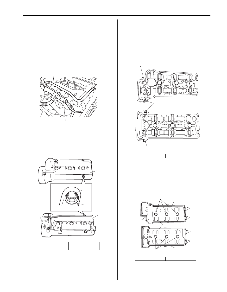
2) Remove heater outlet pipe (1).
3) Detach engine harness (2) from cylinder head
covers.
4) Disconnect ignition coil couplers and remove ignition
5) Remove cylinder head covers (1).
Installation
1) Clean sealing surfaces on cylinder heads and
covers.
2) Remove oil, old sealant, and dust from sealing
surfaces. After cleaning, apply sealant “A” to cylinder
heads sealing surface area as shown in figure.
“A”: Water tight sealant 99000–31250 (SUZUKI
Bond No.1207F)
3) Install new spark plug hole gaskets (3) and new
cylinder head cover gaskets (2) to head covers (1).
4) Apply sealant “A” to cylinder head gaskets searing
surface area as shown in figure.
“A”: Water tight sealant 99000–31250 (SUZUKI
Bond No.1207F)
[A]: RH (No.2) bank
2. Nut
[B]: LH (No.2) bank
3. Seal washer
1
2
I6JB01140027-01
1
2
3
1
[A]
[B]
I6JB01140028-01
[A]: RH (No.2) bank
[B]: LH (No.1) bank
[A]: RH (No.2) bank
[B]: LH (No.1) bank
[A]
[B]
“A”
“A”
“A”
I6JB01140029-03
1
3
2
3
1
[A]
[B]
“A”
“A”
“A”
“A”
“A”
I6JB01140030-03

1D-15 Engine Mechanical:
5) Install cylinder head covers (1) to cylinder heads.
6) Using new seal washers (3), tighten nuts (2)
following sequence (“1” – “4”) as indicated in figure.
Tighten a little at a time and evenly among nuts and
repeat tightening sequence 2 or 3 times before they
are tightened to specified torque.
Tightening torque
Cylinder head cover nut (a): 10.5 N·m (1.1 kgf-
m, 7.5 lb-ft)
7) Install ignition coils and connect ignition coil couplers
8) Clamp engine harness (2) to cylinder head cover.
9) Install heater outlet pipe (1).
10) Install intake manifold and intake collector referring
to “Intake Collector and Intake Manifold Removal
and Installation”.
11) Install electric throttle body assembly referring to
“Electric Throttle Body Assembly Removal and
Installation”.
[A]: RH (No.2) bank
[B]: LH (No.1) bank
1
2
3
[A]
[B]
1
“4”
“3”
“2”
“1”
“1”
“2”
“3”
“4”
I6JB01140031-03
1
2
I6JB01140032-01
Engine Mechanical: 1D-16
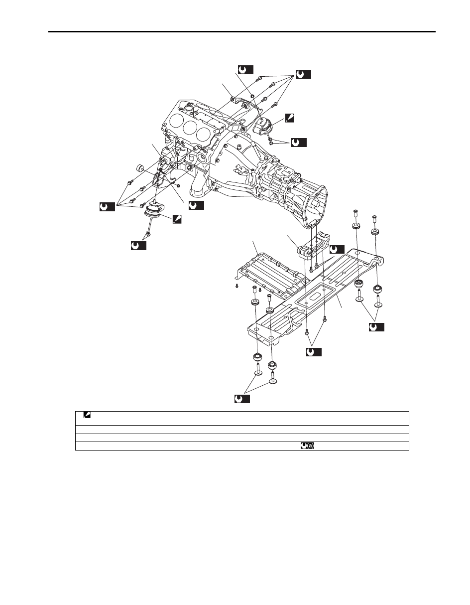
Engine Mounting Components
S6JB0B1406011
4
6
5
1
3
2
(a)
(a)
7
(a)
(a)
(a)
7
(a)
(a)
(a)
(a)
(a)
1
I6JB01140033-02
1. Engine front mounting
Be sure to align dowel pin with dowel hole of engine front mounting bracket.
5. Engine rear mounting
2. Engine front mounting right bracket
6. Engine splash cover (if equipped)
3. Engine front mounting left bracket
7. Engine front mounting nut
4. Engine rear mounting member
: 55 N
⋅m (5.5 kgf-m, 40.0 lb-ft)
Нет комментариевНе стесняйтесь поделиться с нами вашим ценным мнением.
Текст