Suzuki Grand Vitara JB627. Manual — part 82
1D-9 Engine Mechanical:
Air Cleaner Filter Removal and Installation
S6JB0B1406002
Removal
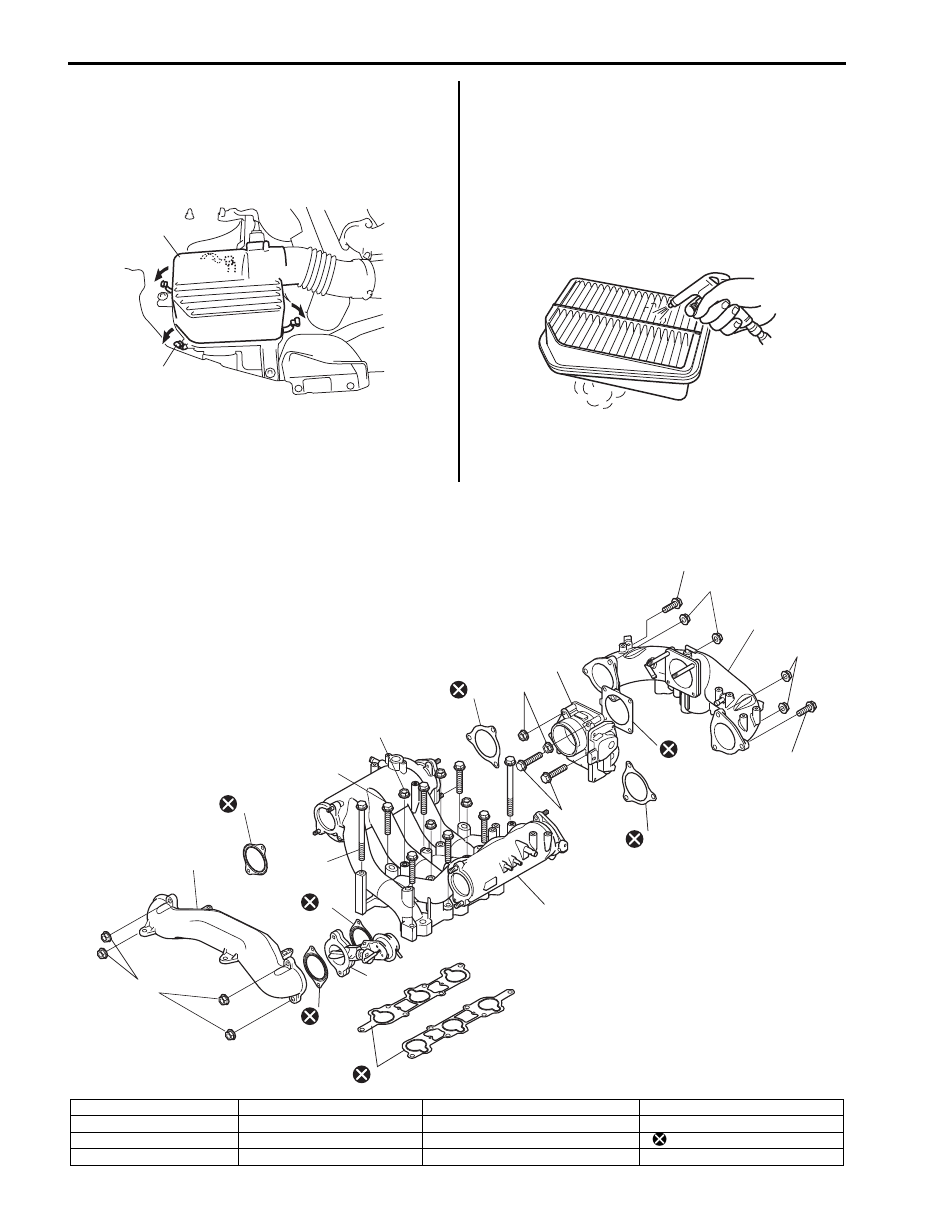
1) Disconnect connector from MAF and IAT sensor.
2) Open air cleaner upper case (1) after unhooking its
clamps (2).
3) Remove air cleaner filter.
Installation
Reverse removal procedure for installation.
Air Cleaner Filter Inspection and Cleaning
S6JB0B1406003
Inspection
Check filter for dirt. Replace if filter is excessively dirty.
Cleaning
When cleaning filter, blow off dust by blowing
compressed air from air outlet side of filter (i.e., the side
facing up when installed in air cleaner case).
Intake Collector and Intake Manifold Components
S6JB0B1406004
1
2
I6JB01140011-01
I6JB01140012-01
1
16
3
4
5
12
10
13
9
8
6
8
9
17
14
7
11
15
2
15
15
7
I6JB01140018-01
1. Intake manifold
6. Intake collector
11. Electric throttle body assembly gasket
16. IMT (Intake manifold tuning) valve
2. Intake manifold gasket
7. Intake collector gasket
12. Electric throttle body assembly nut
17. Surge tank pipe nut
3. Intake manifold bolt (long)
8. Intake collector nut
13. Electric throttle body assembly bolt
: Do not reuse.
4. Intake manifold bolt (short)
9. Intake collector bolt
14. Surge tank pipe
Engine Mechanical: 1D-10
Electric Throttle Body Assembly On-Vehicle
Inspection
S6JB0B1406005
Check electric throttle body assembly referring to
“Electric Throttle Body Assembly On-Vehicle Inspection
in Section 1C”.
Electric Throttle Body Assembly Removal and
Installation
S6JB0B1406006
Removal
1) Release fuel pressure in fuel feed line by referring to
“Fuel Pressure Relief Procedure in Section 1G”.
2) Disconnect negative (–) cable at battery.
3) Drain engine coolant referring to “Cooling System
4) Remove surge tank cover.
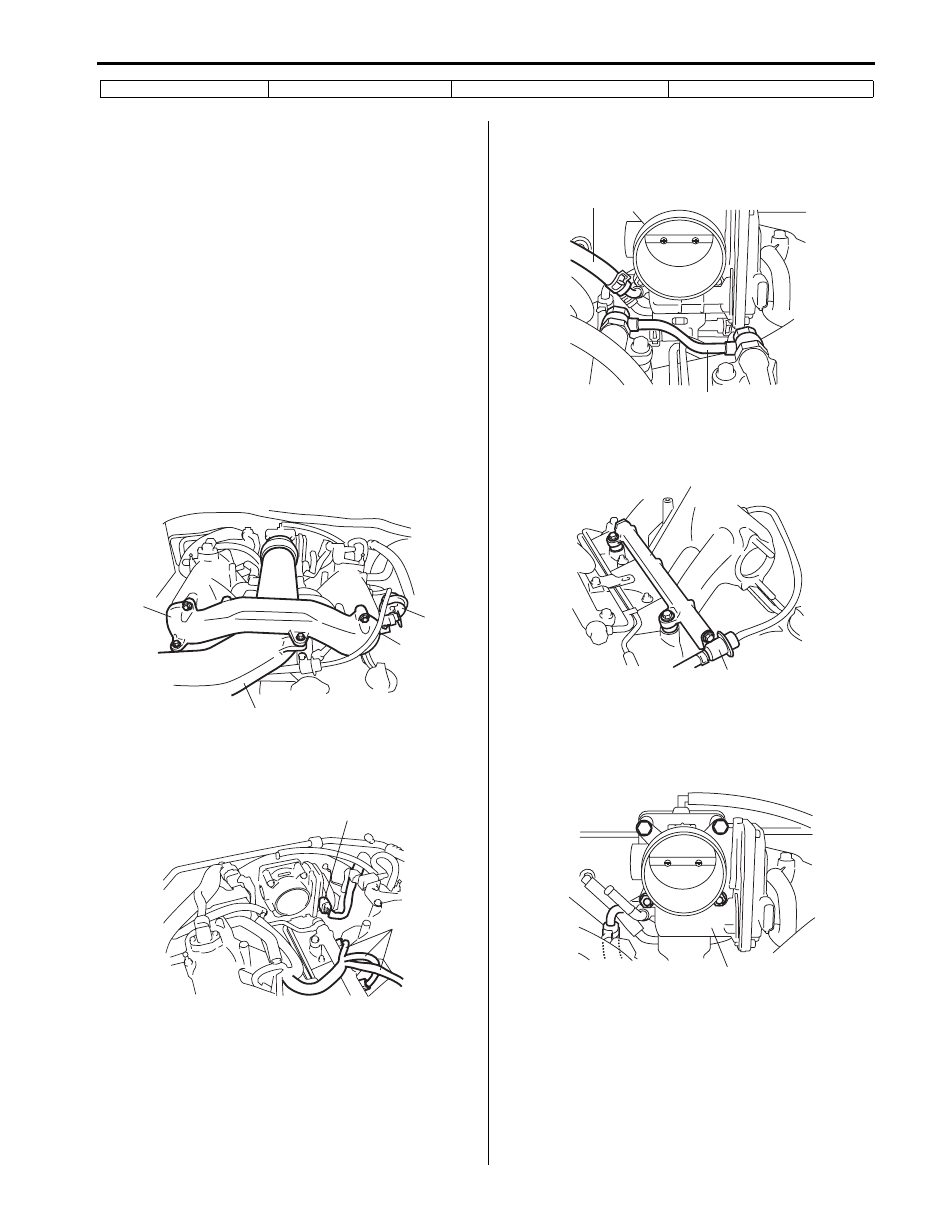
5) Remove intake air pipe (1), surge tank pipe (2) and
IMT valve (3).
6) Disconnect connectors from electric throttle body
assembly (1) and fuel injectors (2) of LH (No.1)
bank.
7) Disconnect fuel connect pipe (1) from delivery pipe.
8) Disconnect water hose (2) from electric throttle body
assembly.
9) Remove LH (No.1) bank delivery pipe (1) with fuel
pressure regulator (2).
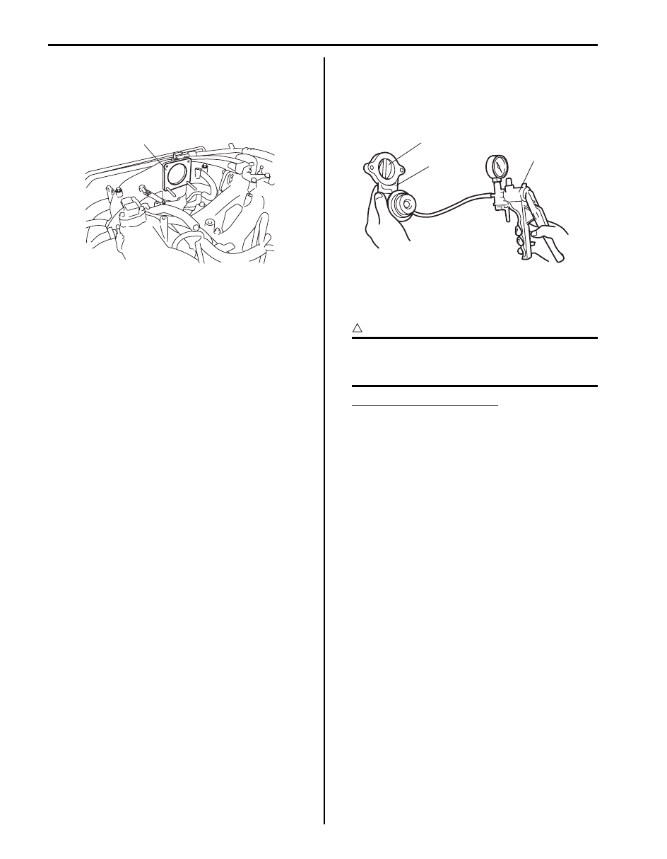
10) Detach electric throttle body assembly (1) from
intake collector.
11) Disconnect water hose (2) from electric throttle body
assembly.
5. Intake manifold nut
10. Electric throttle body assembly
15. Surge tank pipe gasket
2
1
3
I6JB01140112-01
2
1
I6JB01140014-01
2
1
I6JB01140015-01
1
2
I6JB01140016-01
2
1
I6JB01140017-01
1D-11 Engine Mechanical:
Installation
Reverse removal procedure for installation noting the
following.
• Clean mating surfaces and use new throttle body
gasket (1).
• Use new fuel connector pipe gaskets.
• Tighten fuel connector pipe union bolts and delivery
pipe bolts to specified torque referring to “Fuel System
Components in Section 1G”.
• Use new surge tank pipe gaskets.
• Check to ensure that all removed parts are back in
place.
Reinstall any necessary parts which have not been
reinstalled.
• Refill cooling system referring to “Cooling System
Flush and Refill in Section 1F”.
• Upon completion of installation, verify that there is no
fuel leakage at each connection according to “Fuel
Leakage Check Procedure in Section 1G”.
IMT (Intake Manifold Tuning) Valve Removal and
Installation
S6JB0B1406007
Refer to “Electric Throttle Body Assembly Removal and
Installation”.
IMT (Intake Manifold Tuning) Valve Inspection
S6JB0B1406008
1) Connect special tool (A) to IMT valve (1).
Special tool
(A): 09917–47011
2) Apply vacuum to IMT valve (1) and verify that throttle
(2) fully closes within the specified range. If IMT
valve (1) fails this check, replace it.
CAUTION
!
Do not apply above 88 kPa (0.88 kg/cm
2
, 661
mmHg, 880 mbar) of negative pressure.
Damage may occur to IMT valve (1).
IMT valve operation pressure
1.3 – 34 kPa (0.01 – 0.34 kg/cm
2
, 9.8 – 255 mmHg,
13 – 340 mbar)
3) Let the throttle (2) close for 15 seconds with no
vacuum application and inspect throttle travel. If
throttle travel decreases, replace IMT valve (1).
1
I6JB01140109-01
1
(A)
2
I4JA01140010-01
Engine Mechanical: 1D-12
Intake Collector and Intake Manifold Removal
and Installation
S6JB0B1406009
Removal
1) Remove electric throttle body assembly referring to
“Electric Throttle Body Assembly Removal and
Installation”.
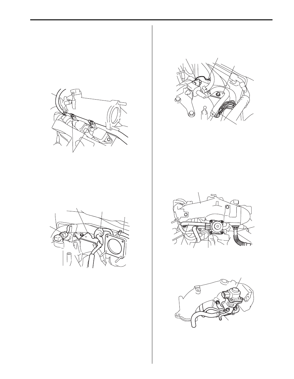
2) Disconnect water hose (1) from heater outlet pipe.
3) Remove heater outlet pipe bolts (2).
4) Disconnect MAP sensor connector (if equipped) (1)
and fuel injector harness connector (2).
5) Remove harness clamp bracket (right side) (3) from
intake collector.
6) Disconnect vacuum hose (4) of EVAP canister purge
valve from intake collector.
7) Disconnect EVAP canister purge valve connector (1)
and ground terminals (2).
8) Remove harness clamp bracket (left side) (3) from
intake collector.
9) With EGR system
a) Disconnect connector from EGR valve assembly
(1).
b) Disconnect EGR pipe (2) and PCV hose (3).
Without EGR system
a) Disconnect PCV hose (3).
10) Detach intake collector (4) from intake manifold, and
then disconnect water hose (5).
11) Remove EGR valve assembly (1) (if equipped) and
PCV pipe (2) from intake collector, if necessary.
1
2
I6JB01140019-01
1
3
2
4
I6JB01140020-01
1
2
3
2
I6JB01140021-01
2
4
3
5
1
I6JB01140022-01
1
2
I6JB01140023-01
Нет комментариевНе стесняйтесь поделиться с нами вашим ценным мнением.
Текст