Suzuki Grand Vitara JB627. Manual — part 222

5A-72 Automatic Transmission/Transaxle:
DTC Troubleshooting
DTC P2764: Torque Converter Clutch (TCC) Circuit Low
S6JB0B5104045
Wiring Diagram
Refer to “DTC P2763: Torque Converter Clutch (TCC) Circuit High”
DTC Detecting Condition and Trouble Area
DTC Confirmation Procedure
WARNING
!
• When performing a road test, select a place where there is no traffic or possibility of a traffic
accident and be very careful during testing to avoid occurrence of an accident.
• Road test should be carried out with 2 persons, a driver and tester, on a level road.
1) Connect scan tool to DLC with ignition switch OFF.
2) Clear DTCs in TCM and ECM memories by using scan tool.
3) Start engine.
4) Keep engine running at idle speed in “P” range for 20 seconds or more.
5) Check DTC, pending DTC and freeze-frame data.
Step
Action
Yes
No
1
Was “A/T System Check” performed?
Go to Step 2.
Go to “A/T System
Check”.
2
Check TCC pressure control solenoid valve circuit for
power supply short
1) Disconnect TCM connectors.
2) Check for proper connection to TCM at terminal “E92-3”
and “E92-5”.
3) If connection is OK, turn ignition switch ON and measure
voltage between terminal “E92-3” of disconnected
harness side TCM connector and ground.
Is it 0 – 2 V?
Go to Step 3.
TCC pressure control
solenoid valve control or
ground circuit is shorted
to power supply circuit.
If circuit is OK, go to
Step 3.
3
Inspection TCC pressure control solenoid valve
1) Inspection TCC pressure control solenoid valve referring
Is check results satisfactory?
Intermittent trouble or
faulty TCM. Check for
intermittent trouble
referring to “Intermittent
and Poor Connection
Inspection in Section
00”. If OK, substitute a
known-good TCM and
recheck.
Replace TCC pressure
control solenoid valve
referring to
“Transmission Fluid
Temperature Sensor
Removal and
Installation”.
DTC Detecting Condition
Trouble Area
Voltage of TCC pressure control solenoid valve TCM terminal is
low although TCM is commanding TCC pressure control solenoid
to turn ON.
(1 driving cycle detection logic)
• TCC pressure control solenoid valve circuit
open or shorted to ground.
• Malfunction of TCC pressure control solenoid
valve
• TCM

Automatic Transmission/Transaxle: 5A-73
DTC Troubleshooting
Step
Action
Yes
No
1
Was “A/T System Check” performed?
Go to Step 2.
Go to “A/T System
Check”.
2
Check TCC pressure control solenoid valve circuit for
ground short
1) Disconnect TCM connectors.
2) Check for proper connection to TCM at terminals “E92-
3” and “E92-5”.
3) If connection is OK, check continuity between terminal
“E92-5” of disconnected harness side TCM connector
and ground.
Is continuity indicated?
TCC pressure control
solenoid valve control
and ground circuit is
shorted to ground. If
circuit is OK, go to Step
4.
Go to Step 4.
3
Check TCC pressure control solenoid valve circuit for
open
1) Check resistance between terminal “E92-3” and “E92-5”
of disconnected harness side TCM connector.
Is it infinity?
TCC pressure control
solenoid valve control
and ground circuit is
open. If circuit is OK, go
to Step 4.
Go to Step 4.
4
Inspection TCC pressure control solenoid valve
1) Inspection TCC pressure control solenoid valve referring
Is check results satisfactory?
Intermittent trouble or
faulty TCM. Check for
intermittent trouble
referring to “Intermittent
and Poor Connection
Inspection in Section
00”. If OK, substitute a
known-good TCM and
recheck.
Replace TCC pressure
control solenoid valve
referring to “Solenoid
Valves (Shift Solenoid-
A, Shift Solenoid-B,
Shift Solenoid-E, TCC
Solenoid, Pressure
Control Solenoid-A,
Pressure Control
Solenoid-B, and
Pressure Control
Solenoid-C) Removal
and Installation”.
5A-74 Automatic Transmission/Transaxle:
DTC U0073: Control Module Communication Bus Off
S6JB0B5104046
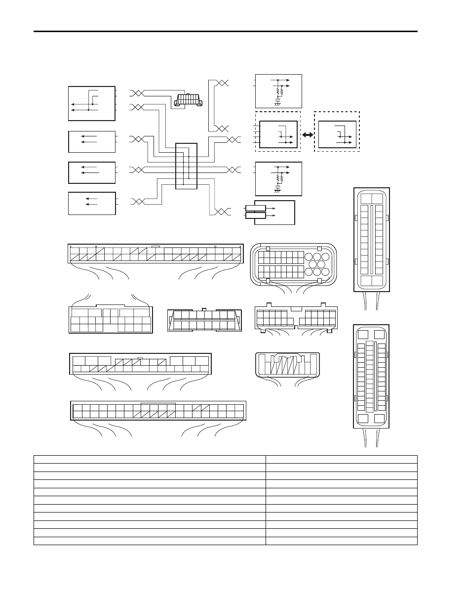
Wiring Diagram
WHT
RED
WHT
RED
G44-18
G44-19
G44
[A]
[B]
[C]
[H]
[G]
1
2
3
4
5
6
7
8
9
10
11
14
15
16
36
34 33 32
30 29
24 23
37
18
19
20
G28-8
G28-10
WHT/BLU
WHT/BLU
WHT/RED
WHT/RED E23-9
E23-17
WHT
RED
WHT
RED
E92-17
E92-7
WHT
RED
E91-22
E91-23
WHT
RED
RED
G31-1
G31-3
G31-4
6
5
16 15 14 13 12 11
4 3
24 23
21
22
10 9
8
7
2
1
19
20
18 17
E92
E23
1
2
3
4
5
6
7
8
9
10
11
17
1615141312
2221201918
G28
[F]
G31
E91
1
2
3
4
7
8
9
10
11
14
15
16
36
34
35
24 23
21
22
28 27
25
26
37
39 38
40
18 17
13 12
19
20
1
2
3
10
11
12
16
17
18
15 14 13
19
20
21
25
26
5
6
[I]
E53
[E]
E03
15
16
17
18
19
20
21
22
23
24
25
2
3
4
5
6
7
8
9
10
11
12
1
13
14
26
G31-2
WHT
1
2
3
4
9
5
6
8
7
E03-12
E03-10
E03-6
E03-8
10
11
E53-13
E53-42
E53-44
E53-46
17
18
19
20
21
22
23
24
25
26
27
28
29
30
31
33
34
35
36
37
38
39
40
32
1
2
3
4
5
6
7
8
9
10
11
12
13
14
15
16
[D]
8 7
6 5 4 3
2 1
9
10
11
12
13
14
15
16
16
1
15
2
3
4
5
6
7
8
9
10
11
12
13
14
17
18
19
20
21
22
23
24
25
26
27
28
29
30
31
32
33
34
35
36
37
38
39
40
41
42
43
44
45
46
47
[J]
G45
10 9
3 2 1
WHT
RED G45-9
G45-10
I6JB0B510006-01
[A]: Keyless start control module connector (viewed from harness side)
2. 4WD control module
[B]: ECM connector (viewed from harness side)
3. TCM
[C]: TCM connector (viewed from harness side)
4. Keyless start control module (if equipped)
[D]: DLC connector (viewed from harness side)
5. DLC
[E]: ABS hydraulic unit/control module connector (viewed from harness side)
6. ECM
[F]: Combination meter connector (viewed from harness side)
7. ABS hydraulic unit/control module
[G]: 4WD control module connector (viewed from harness side)
8. Combination meter
[H]: BCM connector (viewed from harness side)
9. Junction connector
[I]: ESP
® control module connector (viewed from harness side)
10. ESP
® control module (ESP® model)
[J]: Steering angle sensor connector (viewed from harness side)
11. Steering angle sensor (ESP
® model)
1: BCM

Automatic Transmission/Transaxle: 5A-75
DTC Detecting Condition and Trouble Area
DTC Confirmation Procedure
1) Connect scan tool to DLC with ignition switch turned OFF.
2) Turn ON ignition switch and clear DTC by using scan tool.
3) Start engine and run it for 1 min. or more.
4) Check DTC and pending DTC.
DTC Detecting Condition
Trouble Area
Transmission error that is inconsistent between transmission
data and transmission monitor (CAN bus monitor) data is
detected more than 7 times continuously.
(1 driving cycle detection logic)
• ECM
• TCM
• Combination meter
• BCM
• ABS or ESP
® control module
• 4WD control module
• Keyless start control module (if equipped)
• Steering angle sensor (ESP
® model)
• CAN communication line circuit
Нет комментариевНе стесняйтесь поделиться с нами вашим ценным мнением.
Текст