Suzuki Grand Vitara JB627. Manual — part 220

5A-64 Automatic Transmission/Transaxle:
DTC P1702: Internal Control Module Memory Check Sum Error
S6JB0B5104037
DTC Detecting Condition and Trouble Area
NOTE
DTC P1702 can never be cleared once it has been set.
1) Ignition switch OFF.
2) Replace TCM.
3) Repeat “A/T System Check”.
DTC P1703: CAN Invalid Data - TCM
S6JB0B5104038
DTC Detecting Condition and Trouble Area
DTC Troubleshooting
DTC Detecting Condition
Trouble Area
An internal TCM fault is detected by TCM
(1 driving cycle detection logic)
• TCM
DTC Detecting Condition
Trouble Area
When abnormality on the gear shift control signal from ECM is
detected by TCM, TCM sets DTC P1703.
(1 driving cycle detection logic)
• Engine control system
• TCM
• ECM
Step
Action
Yes
No
1
Was “A/T System Check” performed?
Go to Step 2.
Go to “A/T System
Check”.
2
DTC Check
Check DTC in ECM referring to “DTC Check in Section 1A”.
Is there any DTC(s)?
Go to applicable DTC
troubleshooting.
Substitute a known-
good ECM and recheck.
Automatic Transmission/Transaxle: 5A-65
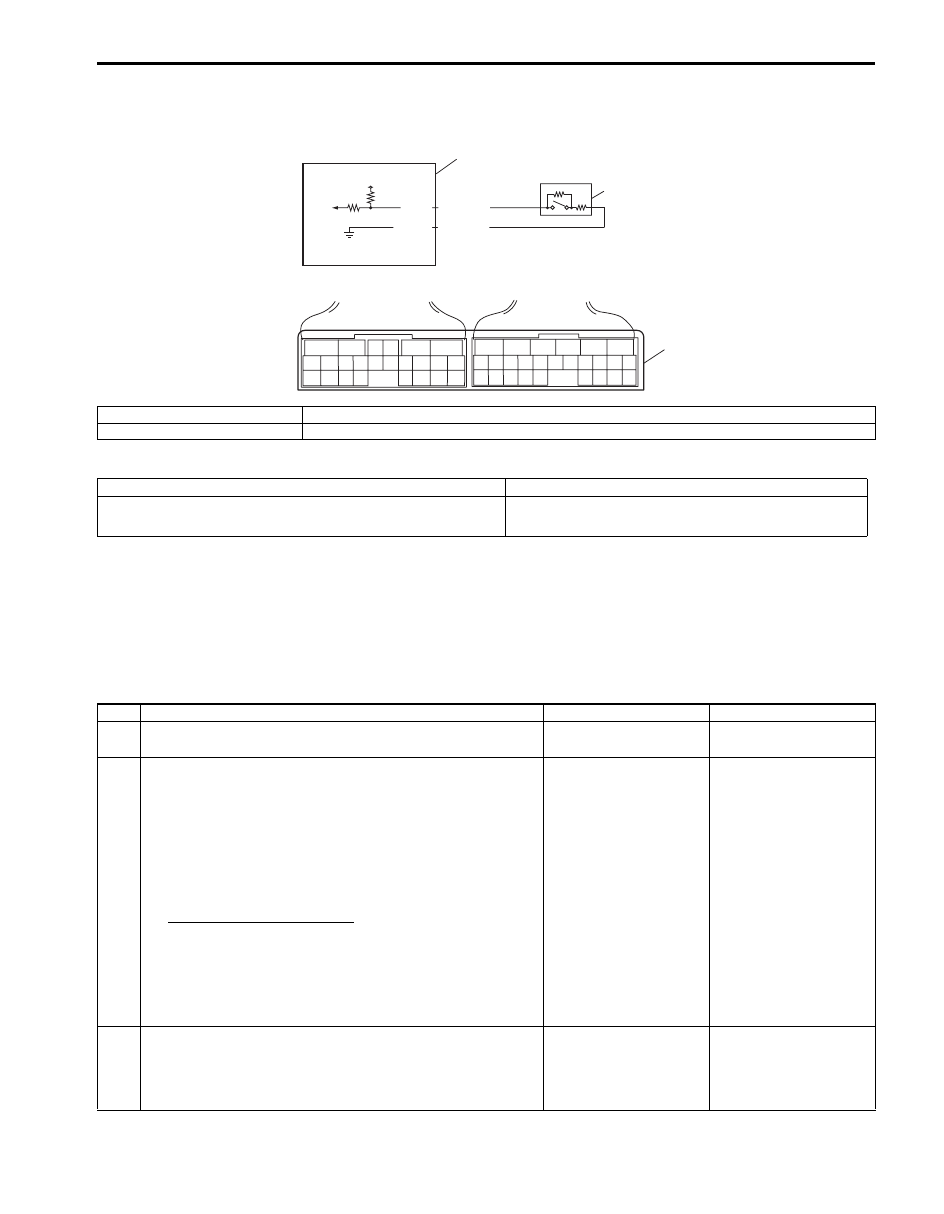
DTC P1723: Range Select Switch Malfunction
S6JB0B5104039
Wiring Diagram
DTC Detecting Condition and Trouble Area
DTC Confirmation Procedure
1) Connect scan tool to DLC with ignition switch OFF.
2) Clear DTCs in TCM and ECM memories by using scan tool.
3) Start engine and run it for 20 sec. or more.
4) Check DTC, pending DTC and freeze-frame data.
DTC Troubleshooting
5V
2
1
3
6
5
16 15 14 13 12 11
4 3
24 23
21
22
10 9
8
7
2
1
19
20
18 17
E92
17 16
26 25
15 14
6
5
3
4
2
13 12
23 22
24
11 10 9
21 20 19
8 7
18
1
E93
E93-9
E93-21
YEL/RED
YEL/BLK
I6JB01510016-01
1. “4” position switch
3. Terminal arrangement of TCM connector (viewed from harness side)
2. TCM
DTC detecting condition
Trouble area
“4” position switch signal is inputted out of specified value.
(1 driving cycle detection logic but MIL does not light up)
• “4” position switch or its circuit malfunction
• TCM
Step
Action
Yes
No
1
Was “A/T System Check” performed?
Go to Step 2.
Go to “A/T System
Check”.
2
Check “4” position switch circuit
1) Disconnect TCM connector with ignition switch OFF.
2) Check fir proper connection to “4” position switch at
“E93-9” and “E93-21” terminals.
3) If OK, check resistance of switch circuit between
terminals “E93-9” and “E93-21” of disconnected harness
side TCM connector.
“4” position switch circuit
Shift selector laver to “P”, “N” or “D” range: 3.96 –
4.04 k
Ω
Shift selector lever to “R”, “4”, “3”, or “L”, range:
0.99 – 1.01 k
Ω
Is check result as specified?
Intermittent trouble or
faulty TCM. Check for
intermittent trouble
referring to “Intermittent
and Poor Connection
Inspection in Section
00”. If OK, substitute a
known-good TCM and
recheck.
Go to Step 3.
3
Check “4” position switch
Check “4” position switch referring to ““4” Position Switch
Inspection”
Is check result as specified?
Replace “4” position
switch.
“4” position switch
circuit is malfunction.

5A-66 Automatic Transmission/Transaxle:
DTC P1874: 4L Switch Circuit Malfunction (Short)
S6JB0B5104040
Wiring Diagram
DTC Detecting Condition and Trouble Area
DTC Confirmation Procedure
1) Connect scan tool to DLC with ignition switch OFF.
2) Clear DTCs in TCM and ECM memories by using scan tool.
3) Start engine and transfer position switch to “4H” position.
4) Keep engine running at idle speed for 10 seconds or more with select “D” range.
5) Start vehicle and increase vehicle speed to about 60 km/h (37 mile/h) for 2 minutes.
6) Stop vehicle.
7) Check DTC, pending DTC and freeze frame data.
DTC Troubleshooting
12V
12V
PNK/WHT
BLK
E93-4
1
2
4
3
6
5
16 15 14 13 12 11
4 3
24 23
21
22
10 9
8
7
2
1
19
20
18 17
E92
17 16
26 25
15 14
6
5
3
4
2
13 12
23 22
24
11 10 9
21 20 19
8 7
18
1
E93
I5JB0A510026-01
1. 4L/N switch
3. 4WD control module
2. TCM
4. Terminal arrangement of TCM connector (viewed from harness side)
DTC detecting condition
Trouble area
Actual transfer position is 4H although TCM detected 4L/N switch is
turned ON with vehicle speed between 29 km/h (18 mile/h) and 88 km/
h (55 mile/h).
(1 driving cycle detection logic)
• 4L/N switch or its circuit
• TCM
Step
Action
Yes
No
1
Vehicle speed signal check
1) Check DTC in ECM and ABS control module referring to
“DTC Check in Section 1A” and “DTC Check in Section
4E”.
Is there DTC P0500: Vehicle speed sensor (VSS)
malfunction in ECM and/or DTC C1021, C1022, C1025,
C1026, C1031, C1032, C1035 and/or C1036 in ABS control
module?
Go to applicable DTC
diag. flow.
Go to Step 2.
2
Was “A/T System Check” performed?
Go to Step 2.
Go to “A/T System
Check”.
3
Do you have SUZUKI scan tool?
Go to Step 4.
Go to Step 5.

Automatic Transmission/Transaxle: 5A-67
DTC P1875: 4L Switch Circuit Malfunction (Open)
S6JB0B5104041
Wiring Diagram
Refer to “DTC P1874: 4L Switch Circuit Malfunction (Short)”.
DTC Detecting Condition and Trouble Area
DTC Confirmation Procedure
1) Connect scan tool to DLC with ignition switch OFF.
2) Clear DTCs in TCM and ECM memories by using scan tool.
3) Start engine and transfer position switch to “4L” position.
4) Keep engine running at idle speed for 10 seconds or more with select lever “D” range.
5) Start vehicle and increase vehicle speed to about 50 km/h (31 mile/h) in “4L” position for 2 minutes.
6) Stop vehicle.
7) Check DTC, pending DTC and freeze-frame data.
4
4L switch and its circuit check
1) Connect SUZUKI scan tool to DLC with ignition switch
OFF.
2) Turn ignition switch ON.
3) Select “DATA LIST” mode on scan tool.
4) Check 4L/N switch signal (ON or OFF) on display when
turning transfer position switch to each position.
4L/N switch specifications (scan tool)
“4H” position: OFF
“4L” position: ON
Is OFF / ON displayed as described above?
Intermittent trouble of
faulty TCM. Check for
intermittent referring to
“Intermittent and Poor
Connection Inspection
in Section 00”. If OK,
substitute a known-
good TCM and recheck.
Go to Step 6.
5
4L/N switch and its circuit check
1) Turn ignition switch ON.
2) Check terminal voltage “E93-4” of TCM connector
connected when turning transfer position switch to each
position.
4L/N switch specifications
“4H” position: 10 – 14 V
“4L” position: 0 – 1 V
Is voltage as specified?
Intermittent trouble or
faulty TCM. Check for
intermittent trouble
referring to “Intermittent
and Poor Connection
Inspection in Section
00”. If OK, substitute a
known-good TCM and
recheck.
Go to Step 6.
6
4L/N switch check
1) Check 4L/N switch for operation referring to “Transfer
Assembly Inspection in Section 3C”.
Is check result satisfactory?
4L/N circuit is shorted to
ground. If wire and
connections are OK,
substitute a known-
good TCM and recheck.
Replace 4L/N switch.
Step
Action
Yes
No
DTC detecting condition
Trouble area
Actual transfer position is 4L although TCM detected low switch is
turned OFF with vehicle speed between 29 km/h (18 mile/h) and 88
km/h (55 mile/h).
(1 driving cycle detection logic)
• 4L/N switch or its circuit
• TCM
Нет комментариевНе стесняйтесь поделиться с нами вашим ценным мнением.
Текст