Suzuki Grand Vitara JB627. Manual — part 265

6C-21 Power Assisted Steering System:
Assembly
1) Apply grease to oil seal (1) lip and apply P/S fluid to
sliding surface of the shaft (2) then insert pulley’s
shaft (2) from oil seal side of the pump body.
“A”: Grease 99000–25010 (SUZUKI Super
Grease A)
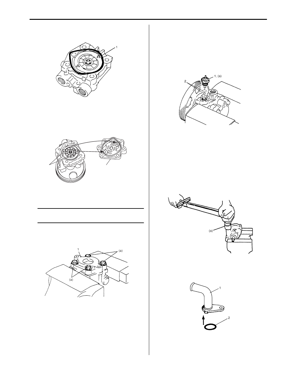
2) Apply power steering fluid to O-rings (1) and fit them
to pump body.
3) Install side plate (1) to pump body.
NOTE
Carefully align the dowel pins on the cam
ring and side plate (1) at bolt hole (2) as
shown in the figure.
4) Apply power steering fluid to sliding surface of rotor
(1).
5) Install rotor (1) to shaft, directing dot (3) marked side
of rotor facing up.
6) Install new snap ring (2) to shaft, then make sure to
fit snap into shaft groove securely.
NOTE
Never reuse the removed snap ring (2).
7) Apply power steering fluid to sliding surface of cam
ring (1).
8) Install cam ring (1) to pump body.
NOTE
Install cam ring by facing side with a mark (2)
toward pump cover.
9) Apply power steering fluid to each vane (2).
10) Install vanes (2) (10 pieces) to rotor (1).
IYSQ01630041-01
I5JB0C630008-01
I5JB0C630009-01
I5JB0C630010-01
I5JB0C630011-01
I5JB0C630012-01
Power Assisted Steering System: 6C-22
11) Apply power steering fluid to O-ring (1).
12) Install O-ring (1) to pump body.
13) Apply power steering fluid to sliding surface of pump
cover and rotor.
14) Match the dowel pins (1) to the holes of the cover
plate (2) as shown and install pump cover to pump
body.
15) Gradually tighten pump cover (1) bolts to diagonally
specified torque.
NOTE
After installing pump cover (1), check to
make sure that shaft can be turned by hand.
Tightening torque
P/S pump cover bolt (a): 28 N·m (2.8 kgf-m, 20.5
lb-ft)
16) Apply power steering fluid to O-ring (2) of pressure
switch.
17) Install O-ring (2) to pressure switch.
18) Install pressure switch (1) to pump body.
Tightening torque
Pressure switch (a): 28 N·m (2.8 kgf-m, 20.5 lb-
ft)
19) Apply power steering fluid to relief valve (flow control
valve).
20) Install relief valve (flow control valve) to pump body.
21) Install flow control spring.
22) Apply power steering fluid to O-rings of plug.
23) Install O-rings to plug.
24) Tighten plug to specified torque.
Tightening torque
Plug (a): 60 N·m (6.0 kgf-m, 43.5 lb-ft)
25) Apply power steering fluid to O-ring (2) of suction
connector (1).
26) Install O-ring (2) to suction connector (1).
I5JB0C630013-01
1
2
I5JB0A630036-01
IYSQ01630049-01
I5JB0C630014-01
IYSQ01630051-01
I5JB0C630015-01
6C-23 Power Assisted Steering System:
27) Install suction connector (1) to pump body as shown
in the figure. Tighten suction connector (1) bolts to
specified torque.
Tightening torque
Suction connector bolt (a): 12 N·m (1.2 kgf-m,
9.0 lb-ft)
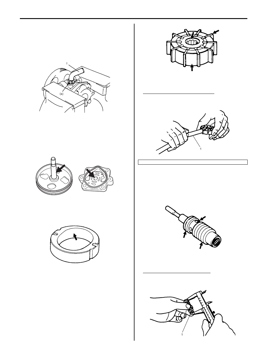
P/S Pump Inspection
S6JB0B6306020
Pump Body, Cover, Side Plate and Shaft
Check sliding surfaces of each part for wear and
damage. If any defect is found, replace pump assembly.
Cam Ring
Check vane sliding surface of cam ring for wear and
damage. If any defect is found, replace pump assembly.
Rotor and Vane
• Check sliding surfaces of rotor and vane for wear and
damage.
• Check clearance between rotor and vane. Replace
pump assembly if any defect is found.
Clearance between rotor and vane
Standard: 0.015 mm (0.0004 in.)
Limit: 0.027 mm (0.0008 in.)
Relief Valve (Flow Control Valve) and Its Spring
• Check fluid passage of relief valve and orifice of
connector for obstruction (clogged).
• Check sliding surface of relief valve for wear and
damage.
• Check free length of relief valve spring (1). Replace if
any defective is found.
Free length of relief valve spring
Standard: 22.0 mm (0.866 in.)
Limit: 19.0 mm (0.748 in.)
I5JB0C630016-01
I5JB0A630051-01
IYSQ01630055-01
1. Thickness gauge
IYSQ01630056-01
IYSQ01630057-01
IYSQ01630058-01
IYSQ01630059-01
Power Assisted Steering System: 6C-24
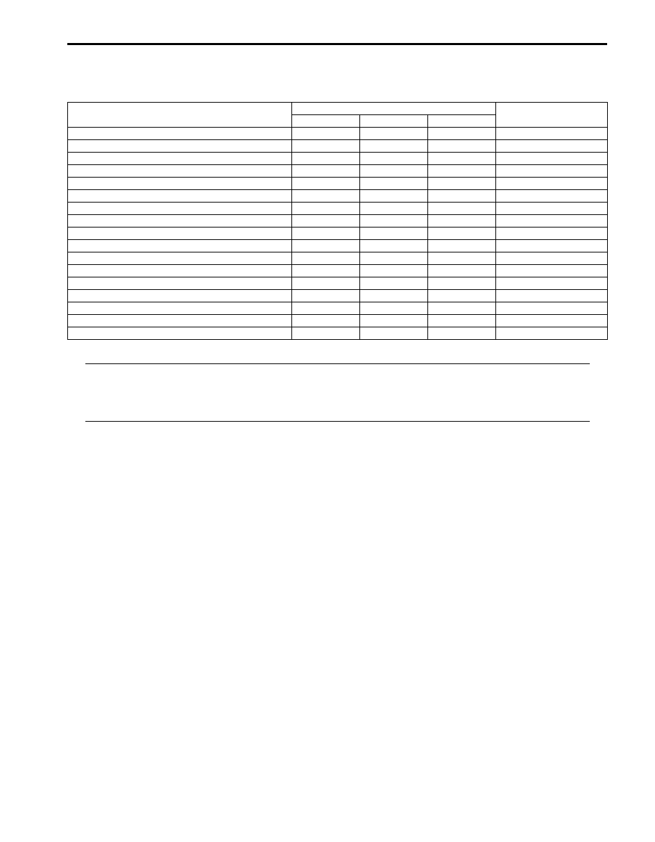
Specifications
Tightening Torque Specifications
S6JB0B6307001
NOTE
The specified tightening torque is also described in the following.
“P/S Gear Case Assembly Components”
“P/S Hose / Pipe Components”
“P/S Pump Components”
Reference:
For the tightening torque of fastener not specified in this section, refer to “Fastener Information in Section 0A”.
Fastening part
Tightening torque
Note
N
⋅m
kgf-m
lb-ft
P/S belt tension pulley bolt
25
2.5
18.5
Tie-rod end nut
43
4.3
31.0
Wheel nut
100
10.0
72.5
Tie-rod end lock nut
65
6.5
47.0
Steering lower shaft bolt
25
2.5
18.5
Gear case high pressure pipe union bolt
35
3.5
25.5
Gear case cylinder pipe flare nut
25
2.5
18.0
Gear case mounting bolt
105
10.5
76
Gear case low pressure pipe union bolt
35
3.5
25.5
Stabilizer bar mount bracket mount bolt
60
6.0
43.0
Tie-rod ball nut
90
9.0
65.0
P/S pump mounting bolt
25
2.5
18.0
High pressure pipe union bolt
60
6.0
43.5
P/S pump cover bolt
28
2.8
20.5
Pressure switch
28
2.8
20.5
Plug
60
6.0 43.5
Suction connector bolt
12
1.2
9.0
Нет комментариевНе стесняйтесь поделиться с нами вашим ценным мнением.
Текст