Suzuki Grand Vitara JB627. Manual — part 264
6C-17 Power Assisted Steering System:
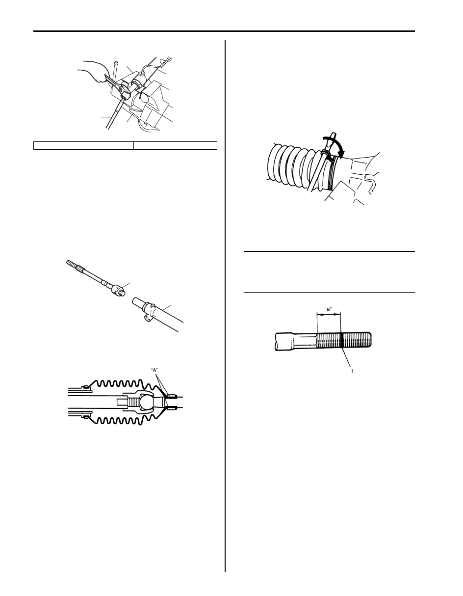
6) Remove tie-rod (1) from steering gear case (2).
Installation
1) Clean threads of both tie-rod and steering gear case
(2).
2) Apply thread lock cement to thread of tie-rod ball nut
(1) and then tighten it to specified torque.
“B”: Thread lock cement 99000–32100 (Thread
Lock Cement 1305)
Tightening torque
Tie-rod ball nut (a): 90 N·m (9.0 kgf-m, 65.0 lb-ft)
3) Apply grease to boot inside “A” indicated in the
figure.
4) Position boot properly in grooves of gear case and
tie-rod. Check to ensure that boot is free from twist
and dent.
5) Clamp boot with clip and wire. Wire should be new
and should go around the boot twice.
Pull its both ends together by screwdriver or such
and make sure that the wire won’t be crossed. Then
twist the ends several times, the twisted ends should
be bent in the circumferential direction.
6) Install tie-rod end lock nut and tie-rod end to tie-rod.
Position lock nut to marking (1) made in removal.
NOTE
When tie-rod was replaced, measure length
“a” on removed tie-rod and use it on new
replacement tie-rod so as to position lock nut
properly.
7) Install steering gear case. Refer to “P/S Gear Case
Assembly Removal and Installation”.
3. Aluminium plate
4. Vise
3
1
4
2
3
I5JB0A630022-01
2
1, (a), “B”
I5JB0A630023-03
IYSQ01630030-01
IYSQ01630035-01
I5JB0A630058-01
Power Assisted Steering System: 6C-18
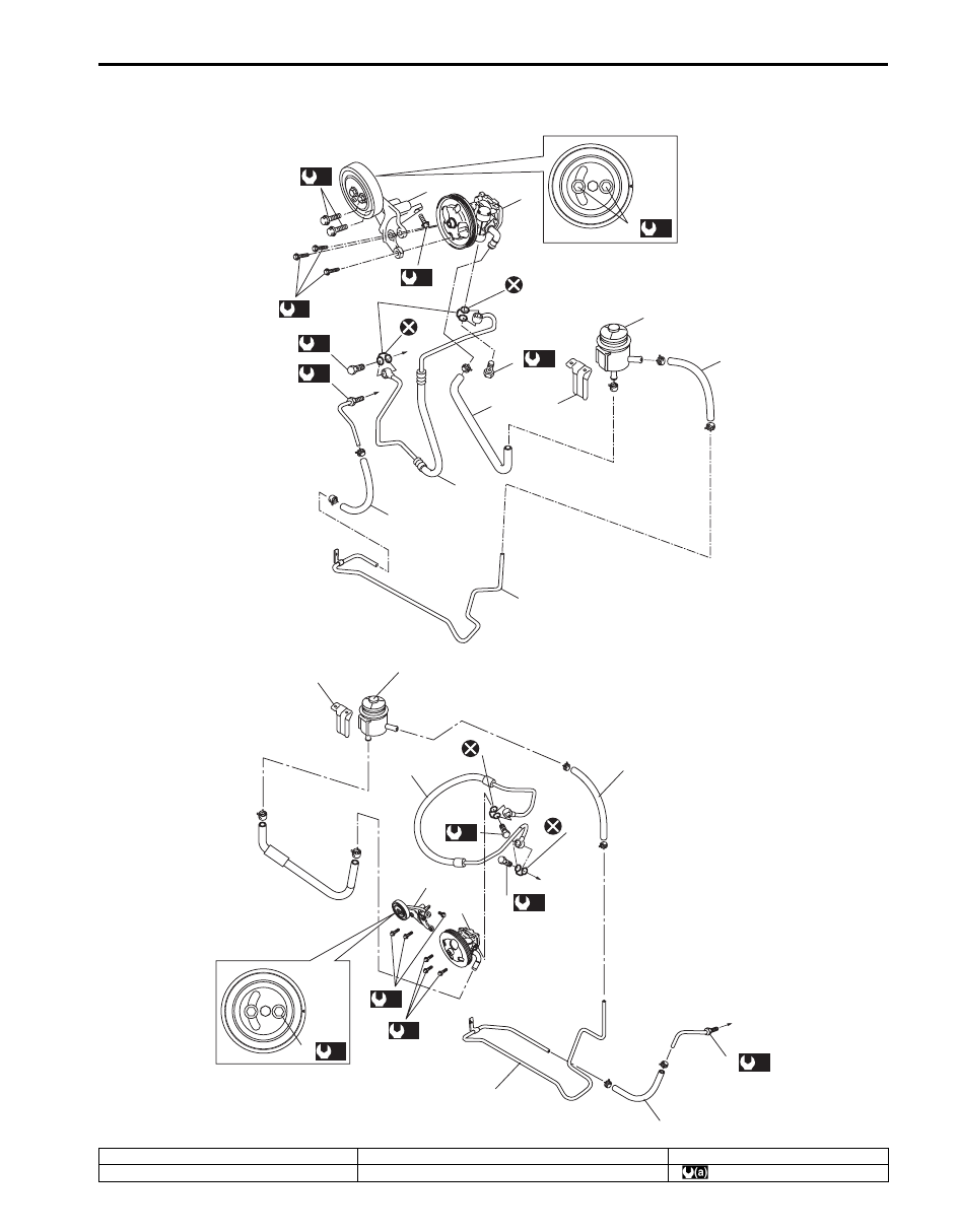
P/S Hose / Pipe Components
S6JB0B6306016
1
3
7
6
5
4
6
6
9
2
15
[A]
[B]
11
(d)
15
(d)
(b)
(a)
10
(c)
12
(c)
13
13
8
8
14
(a)
14
(a)
11
(a)
7
4
6
10
13
9
3
6
6
13
(b)
15
1
2
(c)
12
8
(c)
(d)
8
I6JB0B630006-01
[A]: RHD model
7. P/S fluid reservoir bracket
15. Bracket mount bolt
[B]: LHD model
8. To P/S gear case
: 25 N
⋅m (2.5 kgf-m, 18.0 lb-ft)
6C-19 Power Assisted Steering System:
P/S Pump Removal and Installation
S6JB0B6306017
Removal
NOTE
Be sure to clean each joint of suction and
discharge sides thoroughly before removal.
1) Disconnect negative (–) cable at battery.
2) Take out P/S fluid in reservoir with syringe or such.
3) Disconnect high pressure pipe and suction hose
from power steering pump.
NOTE
As fluid flows out of disconnected joints, put
a receptacle under joints or a plug to pipe.
4) Disconnect pressure switch lead wire at switch
terminal.
5) Remove P/S drive belt referring to “P/S Pump and A/
C Compressor (If Equipped) Drive Belt Removal and
Installation”.
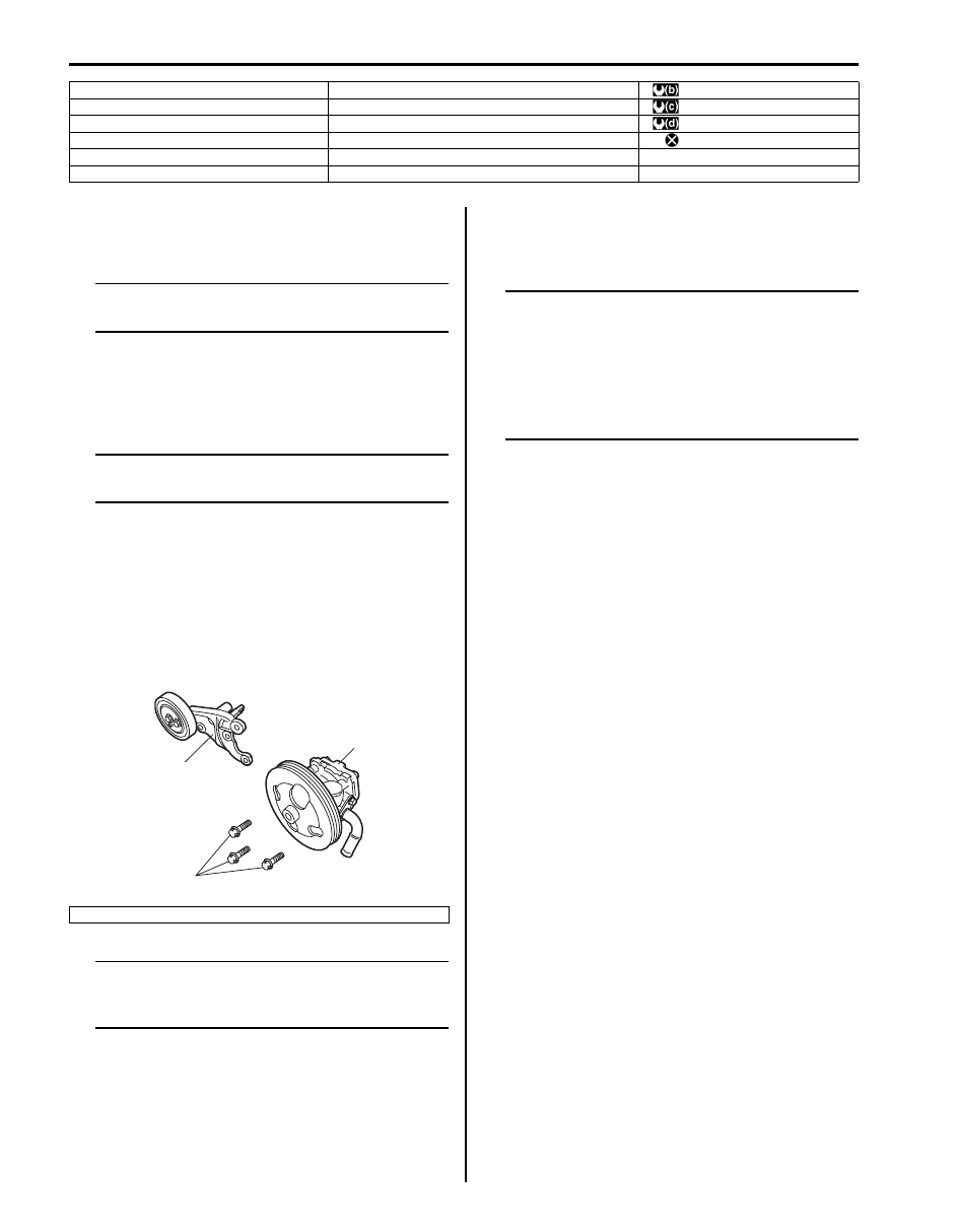
6) Remove P/S pump mounting bolts (1) and then
remove P/S pump.
7) Remove P/S pump (2).
NOTE
Plug each port of removed pump to prevent
dust or any other foreign matter from
entering.
Installation
Reverse removal procedure, and then nothing the
following instructions.
NOTE
• Adjust P/S pump drive belt referring to “P/
S Pump and A/C Compressor (If Equipped)
Drive Belt Inspection and Adjustment”.
• Fill specified power steering fluid after
installation and bleed air without failure
referring to “P/S System Air Bleeding
Procedure”.
Tightening torque
P/S pump mounting bolt: 25 N·m (2.5 kgf-m, 18.0 lb-
ft)
High pressure pipe union bolt: 60 N·m (6.0 kgf-m,
43.5 lb-ft)
1. P/S pump assembly
9. P/S pump high pressure pipe union bolt
: 60 N
⋅m (6.0 kgf-m, 43.5 lb-ft)
2. Bracket
10. P/S gear case high pressure pipe union bolt
: 35 N
⋅m (3.5 kgf-m, 25.5 lb-ft)
3. P/S fluid reservoir
11. P/S pump mounting bolt
: 45 N
⋅m (4.5 kgf-m, 29.0 lb-ft)
4. High pressure hose and pipe
12. P/S gear case low pressure pipe flare nut
: Do not reuse.
5. Suction hose
13. Washer
6. Low pressure return hose
14. P/S belt tension pulley nut
3. P/S pump bracket
3
1
2
I5JB0C630005-01
Power Assisted Steering System: 6C-20
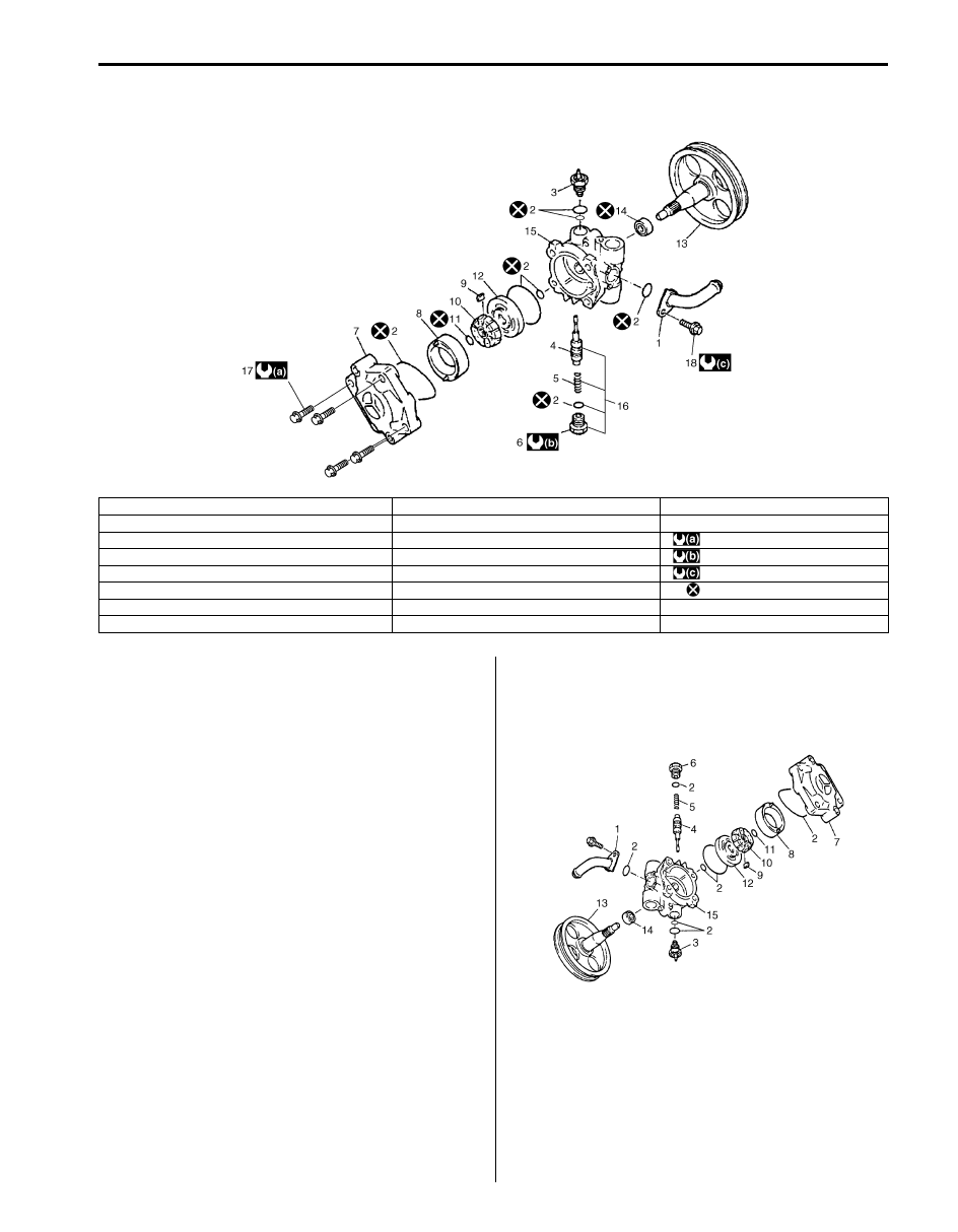
P/S Pump Components
S6JB0B6306018
P/S Pump Disassembly and Assembly
S6JB0B6306019
Disassembly
1) Clean its exterior thoroughly.
2) With aluminum plates placed on vise first, grip pump
body (15) with it.
3) Remove suction connector bolt, suction connector
(1) and O-ring (2) from pump body (15).
4) Remove power steering pressure switch (terminal
set) (3) from pump body (15).
5) Remove plug (6), flow control spring (5) and relief
valve (flow control valve) (4) from pump body (15).
6) Remove cover bolts, pump cover (7) and O-ring (2)
from pump body (15).
7) Remove snap ring (11) from pump shaft (13).
8) Remove vanes (9) from rotor (10).
9) Remove cam ring (8), rotor (10), side plate (12) and
O-rings (2) from pump body (15).
10) Pull out pulley (13) from pump body (15).
11) Remove oil seal (14) from pump body (15).
I5JB0C630006-01
1. Suction connector
9. Vane
17. Cover bolt
2. O-ring
10. Rotor
18. Suction connector bolt
3. Pressure switch
11. Snap ring
: 28 N
⋅m (2.8 kgf-m, 20.5 lb-ft)
4. Flow control valve (Relief valve)
12. Side plate
: 60 N
⋅m (6.0 kgf-m, 43.5 lb-ft)
5. Spring
13. Pulley (pump shaft)
: 12 N
⋅m (1.2 kgf-m, 9.0 lb-ft)
6. Plug
14. Oil seal
: Do not reuse.
7. Pump cover
15. Pump body
8. Cam ring
16. Flow control valve assembly
I5JB0C630007-01
Нет комментариевНе стесняйтесь поделиться с нами вашим ценным мнением.
Текст