Suzuki Grand Vitara JB627. Manual — part 86
1D-25 Engine Mechanical:
Installation
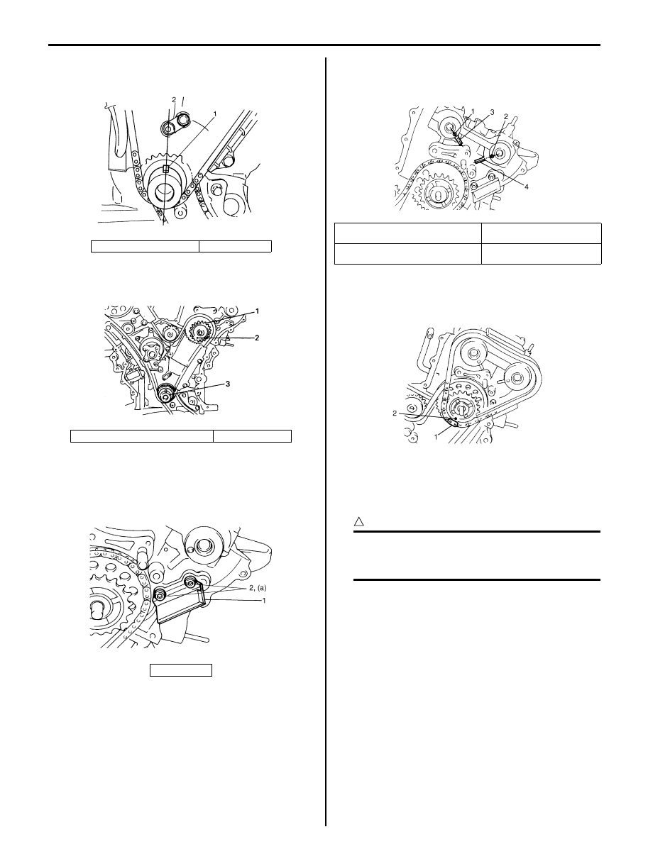
1) Check timing mark on crankshaft as shown in figure.
2) Check timing mark on idler sprocket No.2 (1) as
shown in figure.
3) Install timing chain guide No.4 (1).
Tightening torque
Timing chain guide No.4 bolt (a): 11 N·m (1.1
kgf-m, 8.0 lb-ft)
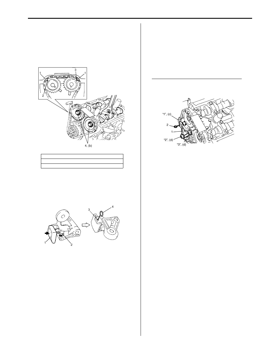
4) Check that knock-pins of intake and exhaust
camshafts are aligned with match marks on cylinder
head as shown in figure.
5) Install by aligning match marks (2) on yellow plate
(1) of LH (No.1) bank 2nd timing chain and idler
sprocket No.2.
6) Install sprockets to intake and exhaust camshafts by
aligning silver plate (1) of LH (No.1) bank 2nd timing
chain, match marks on intake sprocket and exhaust
sprocket respectively.
CAUTION
!
Do not turn camshaft more than necessary. If
turned excessively, valve and piston may get
damaged.
1. Crank timing pulley key
2. Oil jet
2. Match mark of idler sprocket No.2
3. Crankshaft
2. Bolts
I6JB01140044-01
I6JB01140045-01
I6JB01140046-01
1. Knock pin of LH (No.1) bank intake
camshaft
3. Match mark of intake side
2. Knock pin of LH (No.1) bank exhaust
camshaft
4. Match mark of exhaust side
I6JB01140047-01
I6JB01140048-01
Engine Mechanical: 1D-26
7) Install LH (No.1) bank intake and exhaust camshaft
timing sprockets.
To install it, fit a spanner to hexagonal part at the
center of camshaft to hold stationary.
Tightening torque
Camshaft timing sprocket bolt (b): 80 N·m (8.0
kgf-m, 58.0 lb-ft)
8) With latch (2) of tensioner adjuster No.3 returned
and plunger (1) pushed back into body, insert
stopper (pin) (4) into set hole (3).
After inserting it, check that plunger will not come
out.
9) Install timing chain tensioner adjuster No.3 (1) in
tightening order below.
Tightening torque
Timing chain tensioner adjuster No.3 bolt (c):
Tighten 11 N
⋅m (1.1 kgf-m, 7.5 lb-ft) by the
specified procedure
Timing chain tensioner adjuster No.3 nut (d):
Tighten 45 N
⋅m (4.5 kgf-m, 32.5 lb-ft) by the
specified procedure
Tightening order for tensioner bolt and nuts
“1”
→ “2” → “3”
10) Pull out stopper (pin) (2) from set hole.
2. Arrow mark on intake camshaft timing sprocket
3. Arrow mark on exhaust camshaft timing sprocket
4. Sprocket bolt
I6JB01140049-01
IYSQ01143054-01
I6JB01140050-01

1D-27 Engine Mechanical:
11) Turn crankshaft two rotations clockwise then align timing pulley key (1) on crankshaft and oil jet (2) on cylinder
block as shown in figure.
Check each other timing marks that align them shown in figure.
12) Apply oil to timing chains, tensioner adjusters sprockets and guides.
13) Install timing chain cover referring to “Timing Chain Cover Removal and Installation”.
14) Install oil pans referring to “Oil Pan and Oil Pump Strainer Removal and Installation in Section 1E”.
15) Install cylinder head covers referring to “Cylinder Head Covers Removal and Installation”.
16) Install intake manifold, intake collector and electric throttle body assembly referring to “Intake Collector and Intake
Manifold Removal and Installation” and “Electric Throttle Body Assembly Removal and Installation”.
17) Install engine assembly to vehicle referring to “Engine Assembly Removal and Installation”.
I6JB01140051-01
3. Timing mark of RH (No.2) bank 1st timing
chain sprocket
6. Timing mark of LH (No.1) bank 2nd
timing chain
9. Timing mark of RH (No.2) bank 2nd timing chain intake
sprocket
4. Timing mark of RH (No.2) bank 1st timing
chain
7. Timing mark of LH (No.1) bank 2nd
timing chain exhaust sprocket
10. Timing mark of RH (No.2) bank 2nd timing chain exhaust
sprocket
5. Timing mark of LH (No.1) bank 2nd timing
chain intake sprocket
8. Timing mark of LH (No.1) bank 2nd
timing chain
Engine Mechanical: 1D-28
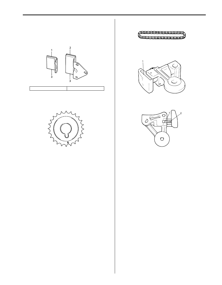
LH (No.1) Bank 2nd Timing Chain and Chain
Tensioner Inspection
S6JB0B1406020
Timing Chain Guide No.4 and No.5
Check shoe (3) for wear or damage.
Camshaft Sprocket
Check teeth of sprocket for wear or damage.
Timing Chain
Check timing chain for wear or damage.
Tensioner Adjuster No.3
• Check shoe (1) for wear or damage.
• Check that latch (1) and tooth surface (2) are free
from damage and latch functions properly.
1. Timing chain guide No.4
2. Timing chain guide No.5
IYSQ01143043-01
I6JB01140052-01
IYSQ01153029-01
IYSQ01143046-01
IYSQ01143047-01
Нет комментариевНе стесняйтесь поделиться с нами вашим ценным мнением.
Текст