Suzuki Grand Vitara JB627. Manual — part 418
10B-21 Body Electrical Control System:
3) Repeat BCM Check Flow Table.
DTC U0155 (No. 0155): Lost Communication with Instrument Panel Cluster (IPC) Control Module
S6JB0BA204018
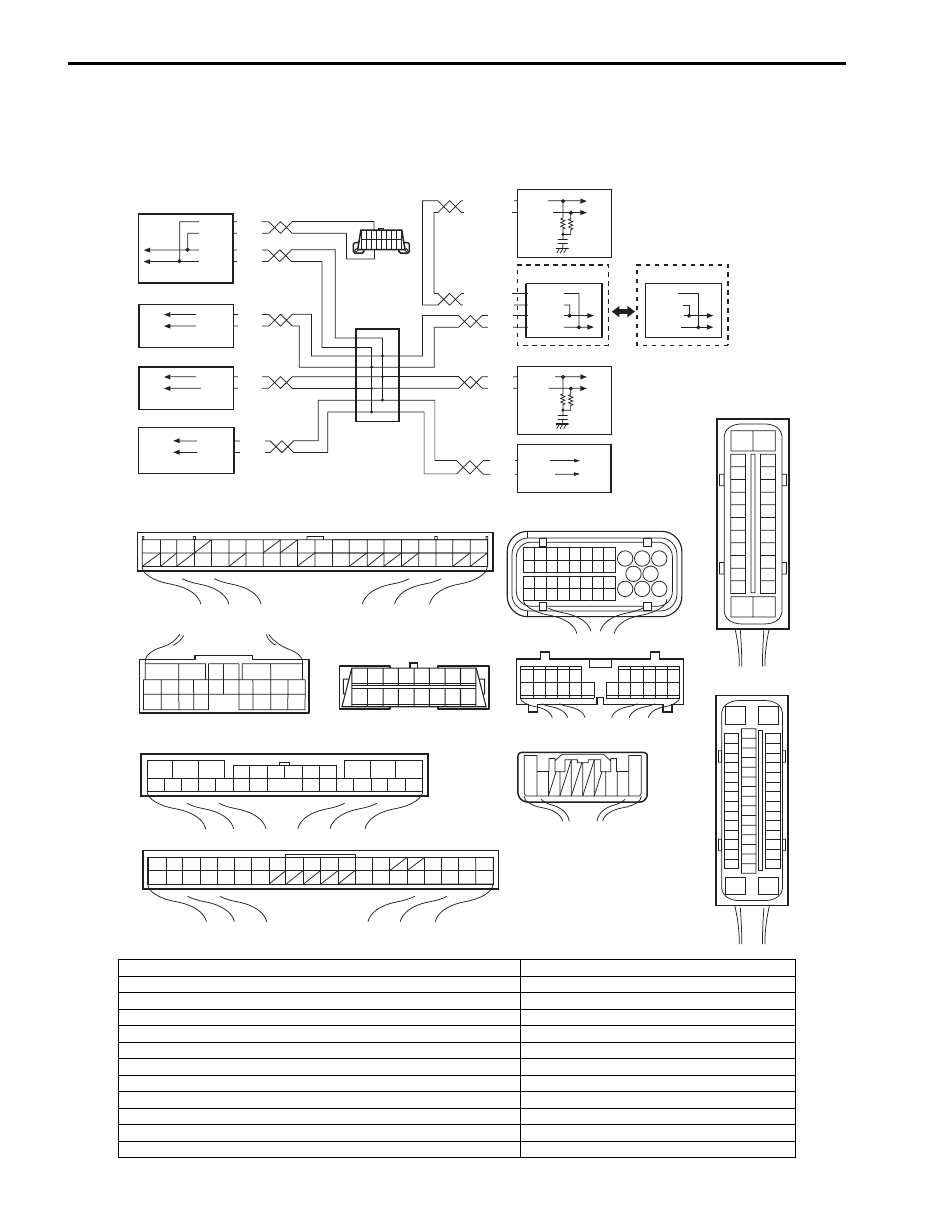
Wiring Diagram
WHT
RED
WHT
RED
G44-18
G44-19
G44
[A]
[B]
[C]
[H]
[G]
1
2
3
4
5
6
7
8
9
10
11
14
15
16
36
34 33 32
30 29
24 23
37
18
19
20
G28-8
G28-10
WHT/BLU
WHT/BLU
WHT/RED
WHT/RED E23-9
E23-17
WHT
RED
WHT
RED
E92-17
E92-7
WHT
RED
E91-22
E91-23
WHT
RED
RED
G31-1
G31-3
G31-4
6
5
16 15 14 13 12 11
4 3
24 23
21
22
10 9
8
7
2
1
19
20
18 17
E92
E23
1
2
3
4
5
6
7
8
9
10
11
17
1615141312
2221201918
G28
[F]
G31
E91
1
2
3
4
7
8
9
10
11
14
15
16
36
34
35
24 23
21
22
28 27
25
26
37
39 38
40
18 17
13 12
19
20
1
2
3
10
11
12
16
17
18
15 14 13
19
20
21
25 24 23 22
26
5
4
6
[I]
E53
[E]
E03
15
16
17
18
19
20
21
22
23
24
25
2
3
4
5
6
7
8
9
10
11
12
1
13
14
26
G31-2
WHT
1
2
3
4
9
5
6
11
8
7
[K]
E03-12
E03-10
E03-6
E03-8
10
[J]
E53-13
E53-42
E53-44
E53-46
17
18
19
20
21
22
23
24
25
26
27
28
29
30
31
33
34
35
36
37
38
39
40
32
1
2
3
4
5
6
7
8
9
10
11
12
13
14
15
16
[D]
8 7
6 5 4 3
2 1
9
10
11
12
13
14
15
16
16
1
15
2
3
4
5
6
7
8
9
10
11
12
13
14
17
18
19
20
21
22
23
24
25
26
27
28
29
30
31
32
33
34
35
36
37
38
39
40
41
42
43
44
45
46
47
[L]
G45
10 9
3 2 1
WHT
RED
7
8
9
G45-9
G45-10
I6JB01A20004-02
[A]: Keyless start control module connector (viewed from harness side)
1. BCM
[B]: ECM connector (viewed from harness side)
2. 4WD control module (if equipped)
[C]: TCM connector (viewed from harness side)
3. TCM (A/T model)
[D]: DLC (viewed from terminal side)
4. Keyless start control module (if equipped)
[E]: ABS control module connector (viewed from terminal side)
5. DLC
[F]: Combination meter connector (viewed from harness side)
6. ECM
[G]: 4WD control module connector (viewed from harness side)
7. ABS control module
[H]: BCM connector (viewed from harness side)
8. Combination meter
[I]: ESP
® control module connector (viewed from terminal side)
9. Junction connector
[J]: Vehicle equipped with ESP
®
10. ESP
® control module
[K]: Vehicle not equipped with ESP
®
11. Steering angle sensor (if equipped)
[L]: Steering angle sensor connector (viewed from harness side)

Body Electrical Control System: 10B-22
DTC Detecting Condition and Trouble Area
DTC Confirmation Procedure
1) Connect scan tool to DLC with ignition switch turned OFF.
2) Turn ON ignition switch and clear DTC by using scan tool.
3) Start engine and run it for 1 min. or more.
4) Check DTC.
DTC Troubleshooting
DTC detecting condition
Trouble area
BCM can not receive CAN data from combination meter
for longer than specified time continuously.
• CAN communication circuit
• BCM
• Combination meter
Step
Action
Yes
No
1
DTC check of BCM
Is DTC U0155 (No. 0155) and DTC U1073 (No. 1073)
detected together?
Go to “DTC U1073 (No.
1073): Control Module
Communication Bus
Off”.
Go to Step 2.
2
Control module connector check
1) Check connection of connectors of all control modules
communicating by means of CAN.
2) Recheck BCM for DTC.
Is DTC U0155 (No. 0155) detected?
Go to Step 3.
Intermittent trouble.
Check for intermittent
referring to “Intermittent
and Poor Connection
Inspection in Section
00”.
3
Combination meter power and ground circuit check
1) Turn ignition switch to ON position.
Do warning lights in combination meter other than key
indicator light light up?
Go to Step 4.
Check combination
meter power and
ground circuit. If circuit
is OK, substitute a
known-good
combination meter and
recheck.
4
CAN communication circuit check
1) Turn ignition switch to OFF position.
2) Disconnect connectors from BCM and combination
meter.
3) Check CAN communication circuit between BCM and
combination meter for open, short and high resistance.
Is each CAN communication circuit in good condition?
Go to Step 5.
Repair circuit.
5
CAN communication circuit check
1) Disconnect connectors of all control modules
communicating by means of CAN.
2) Check CAN communication circuit between control
modules other than Step 4 for open, short and high
resistance.
Is each CAN communication circuit in good condition?
Go to Step 6.
Repair circuit.

10B-23 Body Electrical Control System:
DTC U1073 (No. 1073): Control Module Communication Bus Off
S6JB0BA204013
Wiring Diagram
Refer to “DTC U0155 (No. 0155): Lost Communication with Instrument Panel Cluster (IPC) Control Module”.
DTC Detecting Condition and Trouble Area
DTC Confirmation Procedure
1) Connect scan tool to DLC with ignition switch turned OFF.
2) Turn ON ignition switch and clear DTC by using scan tool.
3) Start engine and run it for 1 min. or more.
4) Check DTC.
6
DTC check of BCM
1) Connect connectors of disconnected control modules
communicating by means of CAN.
2) Disconnect connector of any one of control module other
than BCM.
3) Recheck BCM for DTC.
Is DTC U0155 (No.0155) detected?
Disconnect connectors
of control modules other
than the one whose
connector is
disconnected in Step 2)
one by one and check
that DTC U0155 is
detected by BCM each
time connector is
disconnected. When
DTC U0155 is not
detected by BCM while
checking in this way, go
to description under
“NO” below. If DTC
U0155 is detected by
BCM even when
connectors of all control
modules that use CAN
communication with
BCM are disconnected,
substitute a known-
good BCM and recheck.
Check power and
ground circuit of control
module disconnected in
Step 2). If circuit is OK,
substitute a known-
good control module
disconnected in Step 2)
and recheck.
Step
Action
Yes
No
DTC detecting condition
Trouble area
Transmission error that is inconsistent between
transmission data and transmission monitor (CAN bus
monitor) data is detected more than 7 times continuously.
(1 driving detection logic)
• CAN communication circuit
• Combination meter
• BCM
• 4WD control module (if equipped)
• ABS or ESP
® control module
• TCM (A/T model)
• Keyless start control module (if equipped)
• ECM
• Steering angle sensor (if equipped)

Body Electrical Control System: 10B-24
DTC Troubleshooting
Step
Action
Yes
No
1
Control module connector check
1) Check connection of connectors of all control modules
communicating by means of CAN and reconnect
securely.
2) Recheck DTC and reconnect securely.
Is DTC U1073 detected?
Go to Step 2.
Intermittent trouble.
Check for intermittent
referring to “Intermittent
and Poor Connection
Inspection in Section
00”.
2
CAN communication circuit check
1) Turn ignition switch to OFF position.
2) Disconnect connectors of all control modules
communicating by means of CAN.
3) Check CAN communication circuit between control
modules for open, short and high resistance.
Is each CAN communication circuit in good condition?
Go to Step 3.
Repair circuit.
3
DTC check of BCM
1) Turn ignition switch to OFF position.
2) Connect connectors of disconnected control modules
communicating by means of CAN.
3) Disconnect connector from any one of control modules
other than BCM.
4) Recheck DTC for BCM.
Is DTC U1073 detected?
Disconnect connectors
of control modules other
than the one whose
connector is
disconnected in Step 3)
one by one and check
that DTC U1073 is
detected by BCM each
time connector is
disconnected. When
DTC U1073 is not
detected by BCM while
checking in this way, go
to description under
“NO” below. If DTC
U1073 is detected by
BCM even when
connectors of all control
modules that use CAN
communication with
BCM are disconnected,
substitute a known-
good BCM and recheck.
Check power and
ground circuit of control
module disconnect in
Step 3). If circuit is OK,
substitute a known-
good control module
disconnected in Step 3)
and recheck.
Нет комментариевНе стесняйтесь поделиться с нами вашим ценным мнением.
Текст