Suzuki Grand Vitara JB627. Manual — part 416

10B-13 Body Electrical Control System:
DTC Table
S6JB0BA204004
DTC
(displayed on
SUZUKI scan
tool)
DTC (indicated
by theft
deterrent light)
DTC (displayed on
odometer in
combination meter)
Detected item
Detecting condition
NO DTC
0000
0000
—
No DTC detected
B1133
1133
b1133
Battery voltage too high
Battery voltage too high
B1141
1141
b1141
Outside air temperature
(ambient temperature)
sensor circuit open
Sensor output voltage too
high
B1142
1142
b1142
Outside air temperature
(ambient temperature)
sensor circuit short to
ground
Sensor output voltage too
low
B1150
1150
b1150
Air bag communication
circuit malfunction
Air bag communication
circuit open or short to
ground
B1157
1157
b1157
Air bag deployment signal
input
Air bag deployment signal
inputted
B1170
1170
b1170
EEPROM access error
Memory error
U0155
0155
U0155
Lost communication with
instrument panel cluster
(IPC) control module
Receiving error of BCM from
combination meter for
specified time continuously
U1073
1073
U1073
Control module
communication bus off
Transmitting and receiving
error of BCM for specified
time continuously
U1100
1100
U1100
Lost communication with
ECM
Receiving error of BCM from
ECM for specified time
continuously
U1101
1101
U1101
Lost communication with
TCM
Receiving error of BCM from
TCM for specified time
continuously
U1144
1144
U1144
Lost communication with
keyless start control module
Receiving error of BCM from
keyless start control module
for specified time
continuously
Body Electrical Control System: 10B-14
DTC Check
S6JB0BA204005
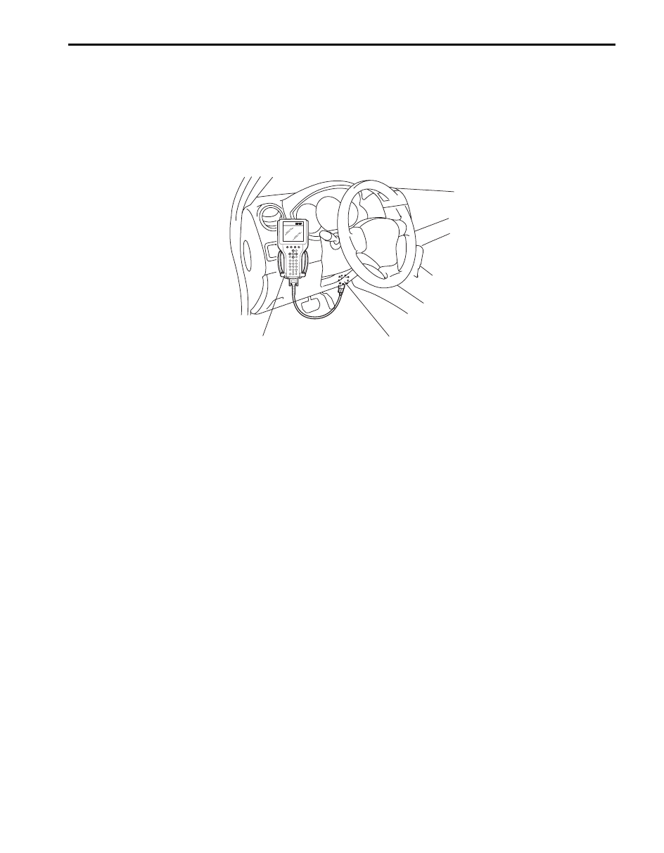
Using SUZUKI Scan Tool
1) Prepare SUZUKI scan tool.
2) With ignition switch turned OFF, connect it to data link connector (DLC) located on underside of instrument panel
of driver’s side.
Special tool
(A): SUZUKI scan tool
3) Turn ignition switch ON.
4) Read DTC according to instructions displayed on SUZUKI scan tool and print it or write it down.
Refer to SUZUKI scan tool operator’s manual for further details.
If communication between SUZUKI scan tool and BCM is not possible, check if SUZUKI scan tool is
communicable by connecting it to BCM in another vehicle. If communication is possible in this case, SUZUKI scan
tool is in good condition. Then check data link connector and serial data line (circuit) in the vehicle with which
communication was not possible.
5) After completing the check, turn ignition switch off and disconnect SUZUKI scan tool from data link connector.
Without Using SUZUKI Scan Tool
1) Turn ignition switch to OFF position.
2) Perform following Steps a) to d) within 10 seconds after ignition switch is turned ON and engine stops.
a) Turn lighting switch to “CLEARANCE” position.
b) Turn lighting switch to “OFF” position.
c) Repeat Steps a) and b) 2 times.
d) Press and release driver side door switch 3 times.
1
(A)
I5JB0AA20005-02
10B-15 Body Electrical Control System:
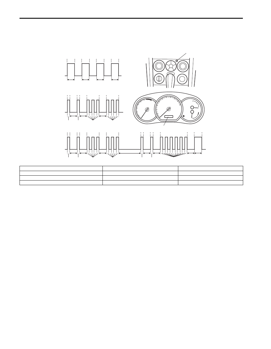
3) Check DTC displayed on odometer of combination meter or read flashing pattern of theft deterrent light which
represents DTC as shown in the following example and write it down.
When more than 2 DTCs are stored in memory, flashing for each DTC starts with the smallest DTC number in
increasing order. Also, DTC is indicated repeatedly until the ignition switch is turned OFF.
4) After completing the check, turn ignition switch to OFF position.
DTC Clearance
S6JB0BA204006
After repair or replace of malfunction part(s), clear all DTCs by performing the following procedure.
Using SUZUKI Scan Tool
1) Connect SUZUKI scan tool to data link connector in the same manner as when making this connection for DTC
check.
2) Turn ignition switch ON and engine stops.
3) Erase DTC according to instructions displayed on scan tool. Refer to scan tool operator’s manual for further
details.
4) After completing the clearance, turn ignition switch off and disconnect scan tool from data link connector.
Without Using SUZUKI Scan Tool
1) Turn ignition switch to OFF position.
2) Perform following Steps a) to d) within 10 seconds after ignition switch is turned ON and engine stops.
a) Turn lighting switch to “CLEARANCE” position.
b) Turn lighting switch to “OFF” position.
c) Repeat Steps a) and b) 3 times.
d) Press and release driver side door switch 4 times.
3) After completing above Steps, confirm that no malfunction DTC is detected.
B
A
[B]
[A]
[C]
B
A
B
A
3
1
1
3
3
1
1
3
T2
T1
T1
T1
T1
T2
T2
T2
T1
T1
T1
T1
T2
T2
0
T2
0
T2
0
T2
0
T2
1
1
6
0
T1
T1
T1
T2
T3
T2
T2
T2
1
2
I5JB0AA20011-01
[A]: No DTC (No. 0000)
B: Indicator light turned OFF
1. Theft deterrent light
[B]: DTC B1133 (No. 1133)
T1: 0.3 seconds
2. Odometer
[C]: When 2 DTCs are detected
T2: 1.0 seconds
A: Indicator light turned ON
T3: 3.0 seconds
Body Electrical Control System: 10B-16
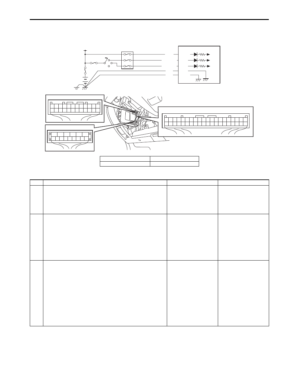
BCM Power Circuit and Ground Circuit Check
S6JB0BA204007
Wiring Diagram
Troubleshooting
7
8
9
10
11
12
13
14
15
6
5
4
3
2
1
G32
24
1
2
3
4
5
6
7
8
9
10
11
12
13
14
15
16
17
18
19
20
21
22
23
G30
1
2
3
4
5
6
7
8
9
10
11
12
13
14
15
16
17
18
19
20
21
22
23
24
25
26
27
28
29
30
31
32
33
34
35
36
37
38
39
40
G31
BLK
BLK
G32-1
G30-12
+B
G32-13
WHT
WHT/BLK G30-2
PPL/RED G30-1
3
2
1
4
I7JB01A20008-01
1. BCM
3. Battery
2. Ignition switch
4. Junction block
Step
Action
Yes
No
1
Fuse check
1) Turn ignition switch to OFF position.
2) Check circuit fuses for condition.
Are circuit fuses in good condition?
Go to Step 2.
Replace fuse and check
for short circuit to
ground.
2
Power supply circuit check
1) Disconnect connectors from BCM.
2) Check for proper connection to BCM connector at
terminal “G32-13”.
3) If OK, then measure voltage between “G32-13” terminal
of BCM and vehicle body ground.
Is voltage 10 – 14 V?
Go to Step 3.
Repair power supply
circuit.
3
Power supply circuit check
1) Check for proper connection to BCM connector at
terminals “G30-1” and “G30-2”.
2) If OK, turn ignition switch ON.
3) Measure voltage between following terminals.
• Between “G30-1” terminal of BCM connector and
vehicle body ground
• Between “G30-2” terminal of BCM connector and
vehicle body ground
Is each voltage 10 – 14 V?
Go to Step 4.
Repair power supply
circuit.
Нет комментариевНе стесняйтесь поделиться с нами вашим ценным мнением.
Текст