Suzuki Grand Vitara JB627. Manual — part 150

3C-4 Transfer:
Function of 4WD Control System Component
S6JB0B3301004
4WD Control System Operation
S6JB0B3301005
Instead of the transfer shift lever assembly, the transfer position (4H, 4H-lock, N and 4L-lock) is shifted automatically
by operating the transfer switch.
The 4WD control module operates the transfer shift actuator according to the transfer switch operation.
Part Name
Function
4L/N switch
Detects transfer shift position combining center differential lock
switch.
Center differential lock switch
Detects transfer shift position combining 4L/N switch.
Transfer switch
Shifts transfer shift position.
N indicator
Indicates transfer is at N position or not.
4L indicator
Indicates transfer is at 4L-lock position or not.
Differential lock indicator
Indicates transfer is at 4H-lock, 4L-lock or not.
Transmission range sensor (N position) (for A/T
model)
Detects A/T is at N range or not.
CPP switch
Detects clutch pedal is depressed or not.
Buzzer incorporated into BCM
• Indicates transfer is at “N” position.
• Warns of prohibited shift operation.
4WD control module
• Controls transfer shifting.
• Diagnoses 4WD control system components.
• Output operation signal of indicators and buzzer to BCM.
Transfer shift actuator
• Consists of transfer shift actuator motor and transfer shift
actuator motor position switch.
• Shifts transfer shift position operating High / Low shift fork and
differential lock shift fork via cams.
• Detects transfer shift actuator motor position.
Diagnosis connector
Indicates DTC on indicators when grounding its diagnosis
terminal.
Transfer: 3C-5
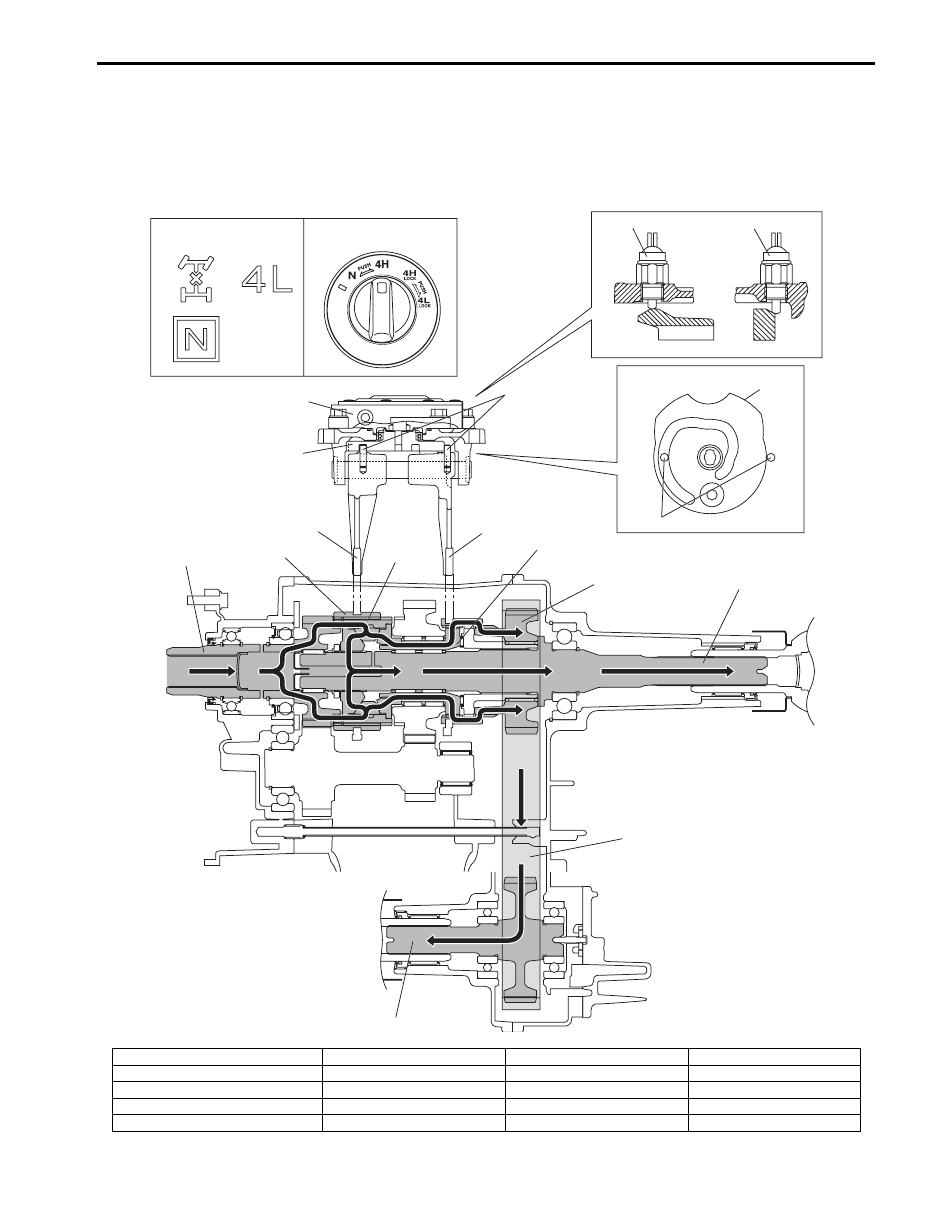
4H (4WD High) Position
The driving force from the transmission is transmitted to the transfer input gear. As the center LSD case and transfer
input gear are engaged via the reduction shift sleeve at this time, the driving force transmitted from the transfer input
gear to the rear output shaft rotates them at the same speed.
Also, driving force from the center LSD is transmitted to the front drive shaft through front drive sprocket. Then, the
front drive sprocket rotates the front output shaft via the drive chain.
[A]
[B]
1
2
5
4
4
3
5
9
8
6
7
11
12
13
14
15
10
I5JB0A332003-02
[A]: Transfer position indicator
4. Shift fork pin
9. Reduction shift sleeve
14. Drive chain
[B]: Transfer switch
5. Shift cam
10. Center LSD case
15. Front output shaft
1. 4L/N switch
6. High / Low shift fork
11. Front drive shaft
2. Center differential lock switch
7. Differential lock shift fork
12. Front drive sprocket
3. Transfer actuator
8. Input gear
13. Rear output shaft

3C-6 Transfer:
4H-lock (4WD High Center Differential Lock) Position
When 4H-lock position is selected from 4H position by turning the transfer switch, the transfer shift control actuator
motor runs and shift cam rotates in the arrow direction “A”. The shift cam shifts the differential lock shift fork in the
arrow direction “B”, and the differential lock clutch sleeve also moves in the arrow direction “B”.
The driving force from the transmission is transmitted from the transfer input gear to the rear output shaft, as in the
case of 4H position. Also, as the front drive shaft and front drive sprocket bush are engaged via differential lock clutch
sleeve, the driving force from the input gear is locked and transmitted to the rear output shaft.
B
[A]
[B]
1
2
4
3
5
7
10
6
8
9
11
12
13
14
A
4
5
I5JB0A332004-03
[A]: Transfer position indicator
3. Transfer actuator
7. Input gear
11. Rear output shaft
[B]: Transfer switch
4. Shift fork pin
8. Differential lock clutch sleeve
12. Front drive shaft
1. 4L/N switch
5. Shift cam
9. Front drive sprocket bush
13. Drive chain
2. Center differential lock switch
6. Differential lock shift fork
10. Front drive sprocket
14. Front output shaft
Transfer: 3C-7
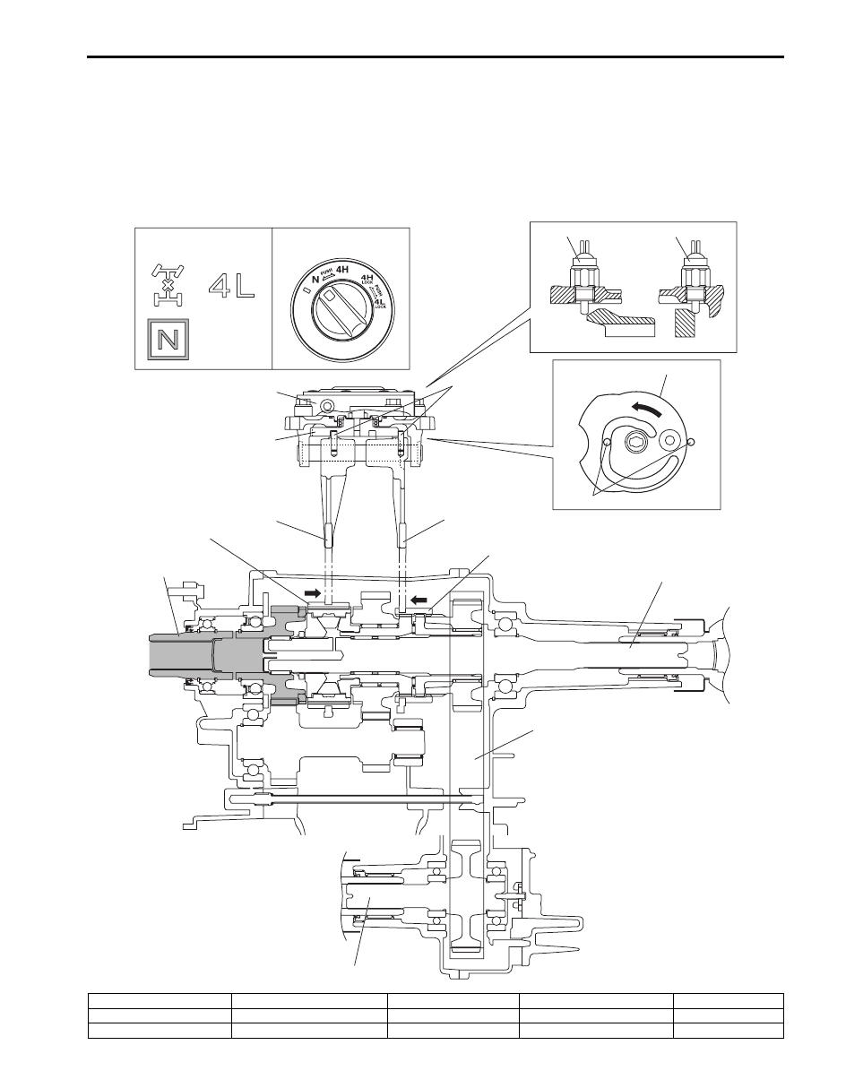
N (Neutral) Position
When N position is selected from 4H position by turning the transfer switch, the transfer shift control actuator motor
runs and shift cam rotates in the arrow direction “A”. The shift cam shifts the High / Low shift fork in the arrow direction
“B”, and the reduction shift sleeve moves in the arrow direction “B”. Also, the shift cam shifts the differential lock shift
fork in the arrow direction “C”, and the differential lock clutch sleeve also moves in the arrow direction “C”.
The driving force from the transmission is transmitted to the transfer input gear. However, as the reduction shift sleeve
is not engaged with the transfer input gear and low gear, the driving force is not transmitted to the rear output shaft and
front output shaft.
A
C
B
[A]
[B]
1
2
5
4
4
3
5
9
8
6
7
11
12
13
10
I5JB0A332005-01
[A]: Transfer position indicator
2. Center differential lock switch
5. Shift cam
8. Input gear
11. Rear output shaft
[B]: Transfer switch
3. Transfer actuator
6. High / Low shift fork
9. Reduction shift sleeve
12. Drive chain
1. 4L/N switch
4. Shift fork pin
7. Differential lock shift fork
10. Differential lock clutch sleeve
13. Front output shaft
Нет комментариевНе стесняйтесь поделиться с нами вашим ценным мнением.
Текст