Suzuki Grand Vitara JB627. Manual — part 285
7B-56 Air Conditioning System:
HVAC Control Module and Its Circuits Inspection
S6JB0B7204032
CAUTION
!
HVAC control module can not be checked by itself.
It is strictly prohibited to connect voltmeter to HVAC control module with couplers disconnected from
it.
HVAC control module and its circuits can be checked at HVAC control module wiring couplers by measuring voltage.
Voltage Check
1) Remove HVAC control module. Refer to “HVAC Control Module Removal and Installation in Section 7A”.
2) Connect HVAC control module and body control module couplers to HVAC control module and body control
module.
3) Check each terminal voltage with couplers connected by referring to “HVAC Control Module Voltage Table: ”.
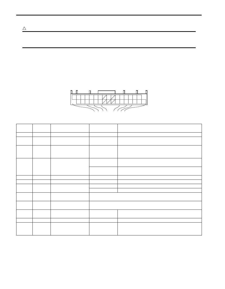
Terminal arrangement of HVAC control module (viewed from harness side)
HVAC Control Module Voltage Table
16 15 14 13 12 11 10
8
6
5
4
3
2
1
32 31 30 29 28 27
23 22 21 20 19 18 17
I5JB0A720030-02
Terminal
Wire
color
Circuit
Normal value
Condition
G52-1
PPL/RED Power supply
10 – 14 V
Ignition switch turned ON.
G52-2
WHT
Electric power source
for back-up
10 – 14 V
Constantly.
G52-3
PPL/WHT
Serial communication
line of data link
connector
10 – 14 V
Ignition switch turned ON.
G52-4
RED/YEL Illumination switch
0 – 1 V
Ignition switch turned ON, lighting switch OFF
position.
10 – 14 V
Ignition switch turned ON, lighting switch ON
position.
G52-5
RED/GRN Illumination ground
0 – 1 V
Constantly.
G52-6
PNK/BLK Theft deterrent light
—
—
G52-8
BLK/RED
Rear defogger driving
signal
10 – 14 V
Ignition switch turned ON, rear defogger switch ON.
0 – 1 V
Ignition switch turned ON, rear defogger switch OFF.
G52-10 YEL/RED
Serial communication
line from BCM
Refer to “Inspection of BCM and Its Circuits in Section 10B”.
G52-11 PNK/GRN
Serial communication
line to BCM
Refer to “Reference waveform No. 1: ”.
G52-12
YEL
Ground for sunload
sensor
0 – 1 V
Constantly.
G52-13 BLK/RED Ground for sensors
0 – 1 V
Constantly.
G52-14 RED/WHT
Output of 5 V power
source for position
sensor of actuators
4 – 6 V
Ignition switch turned ON.

Air Conditioning System: 7B-57
G52-15 RED/BLK
Blower motor control
voltage feedback
Approx. 14 V
Ignition switch turned ON, blower speed selector
OFF.
Approx. 10 V
Ignition switch turned ON, blower speed selector 1st
position.
Approx. 9 V
Ignition switch turned ON, blower speed selector 2nd
position.
Approx. 8 V
Ignition switch turned ON, blower speed selector 3rd
position.
Approx. 6 V
Ignition switch turned ON, blower speed selector 4th
position.
Approx. 5 V
Ignition switch turned ON, blower speed selector 5th
position.
Approx. 4 V
Ignition switch turned ON, blower speed selector 6th
position.
Approx. 2 V
Ignition switch turned ON, blower speed selector 7th
position.
Less than 0.3 V
Ignition switch turned ON, blower speed selector 8th
position.
G52-16 PPL/GRN Blower motor controller
0 – 1 V
Ignition switch turned ON, blower speed selector
OFF.
Approx. 4.2 V
Ignition switch turned ON, blower speed selector 1st
– 7th position.
Approx. 8 V
Ignition switch turned ON, blower speed selector 8th
position.
G52-17
BLK
Ground for HVAC
control module
0 – 1 V
Constantly.
G52-18
PNK
Sunload sensor signal
Approx. 3 V
Ignition switch turned ON, amount of insolation is
500 W/m
2
Approx. 5 V
Ignition switch turned ON, amount of insolation is 0
W/m
2
G52-19 WHT/BLK
Evaporator
temperature sensor
signal
Approx. 3.6 V
Ignition switch turned ON, evaporator temperature 0
°C (32 °F).
Approx. 3.4 V
Ignition switch turned ON, evaporator temperature
10
°C (50 °F).
Approx. 2.4 V
Ignition switch turned ON, evaporator temperature
25
°C (77 °F).
G52-20 BLU/BLK
Inside air temperature
sensor signal
Approx. 2.4 V
Ignition switch turned ON, room temperature 25
°C
(77
°F).
Approx. 3.8 V
Ignition switch turned ON, room temperature 0
°C
(32
°F).
G52-21 WHT/RED
Temperature control
actuator position
sensor signal
Approx. 4.5 V
Ignition switch turned ON, temperature selector MAX
COOL position.
Approx. 1.5 V
Ignition switch turned ON, temperature selector MAX
HOT position.
G52-22 WHT/GRN
Air intake control
actuator position
sensor signal
Approx. 3.8 V
Ignition switch turned ON, air intake selector “REC”
position.
Approx. 1.5 V
Ignition switch turned ON, air intake selector “FRE”
position.
G52-23 WHT/BLU
Air flow control actuator
position sensor signal
Approx. 4.2V
Ignition switch turned ON, air flow selector “VENT”
position.
Approx. 3.2 V
Ignition switch turned ON, air flow selector “BI-
LEVEL” position
Approx. 2 V
Ignition switch turned ON, air flow selector “FOOT”
position.
Approx. 1.5 V
Ignition switch turned ON, air flow selector “DEF /
FOOT” position.
Approx. 0.6 V
Ignition switch turned ON, air flow selector “DEF”
position.
Terminal
Wire
color
Circuit
Normal value
Condition
7B-58 Air Conditioning System:
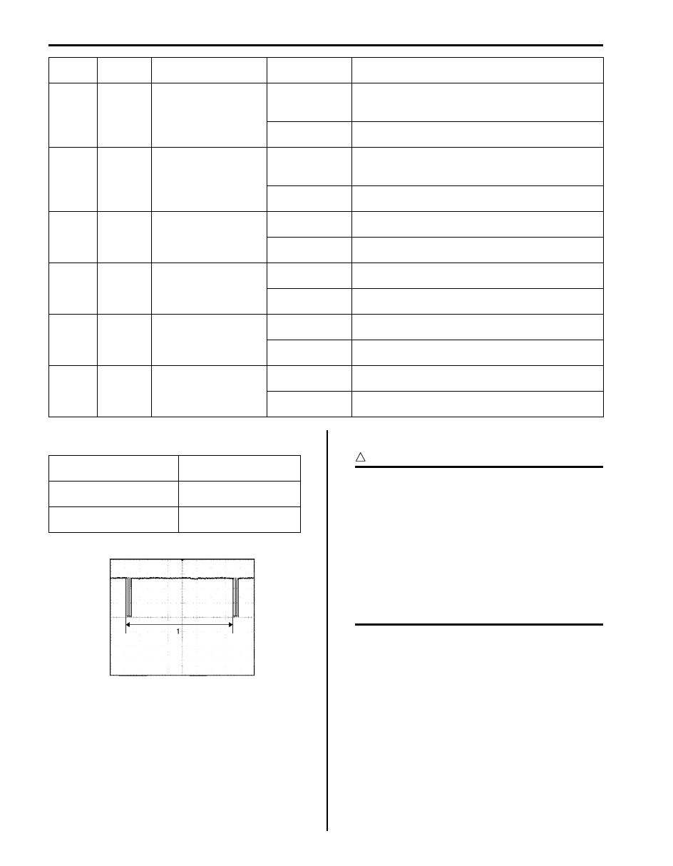
Reference waveform No. 1
Serial communication line to BCM (1)
A/C System Inspection at ECM
S6JB0B7204033
CAUTION
!
• ECM connectors are waterproofed. Each
terminal of the ECM connectors is sealed
up with the grommet. Therefore, do not
measure circuit voltage and resistance by
inserting the tester’s probe into the sealed
terminal at the harness side. Or, ECM and
its circuits may be damaged by water.
• ECM (PCM) cannot be checked by itself.
It is strictly prohibited to connect voltmeter
or ohmmeter to ECM (PCM) with couplers
disconnected from it.
Voltage Check
When checking voltage at ECM terminals related to A/C
system, refer to “Inspection of ECM and Its Circuits in
Section 1A”.
G52-27
GRY
Temperature control
actuator (COOL)
10 – 14 V
Ignition switch turned ON, temperature control
actuator is working in operation from HOT to COOL
position.
0 – 1 V
Ignition switch turned ON, except the above
condition.
G52-28 GRY/BLU
Temperature control
actuator (HOT)
10 – 14 V
Ignition switch turned ON, temperature control
actuator is working in operation from COOL to HOT
position.
0 – 1 V
Ignition switch turned ON, except the above
condition.
G52-29 GRY/RED
Air flow control actuator
(VENT)
10 – 14 V
Ignition switch turned ON, air flow control actuator is
working in operation from DEF to VENT position.
0 – 1 V
Ignition switch turned ON, except the above
condition.
G52-30 GRY/BLK
Air flow control actuator
(DEF)
10 – 14 V
Ignition switch turned ON, air flow control actuator is
working in operation from VENT to DEF position.
0 – 1 V
Ignition switch turned ON, except the above
condition.
G52-31
ORN
Air intake control
actuator (FRE)
10 – 14 V
Ignition switch turned ON, air intake control actuator
is working in operation from REC to FRE position.
0 – 1 V
Ignition switch turned ON, except the above
condition.
G52-32
GRN
Air intake control
actuator (REC)
10 – 14 V
Ignition switch turned ON, air intake control actuator
is working in operation from FRE to REC position.
0 – 1 V
Ignition switch turned ON, except the above
condition.
Terminal
Wire
color
Circuit
Normal value
Condition
Measurement terminal
CH1: “G52-11” to “G52-
17”
Oscilloscope setting
CH1: 5 V / DIV
TIME: 20 ms / DIV
Measurement condition
Ignition switch is at ON
position
I5JB0A720091-01
Air Conditioning System: 7B-59
Repair Instructions
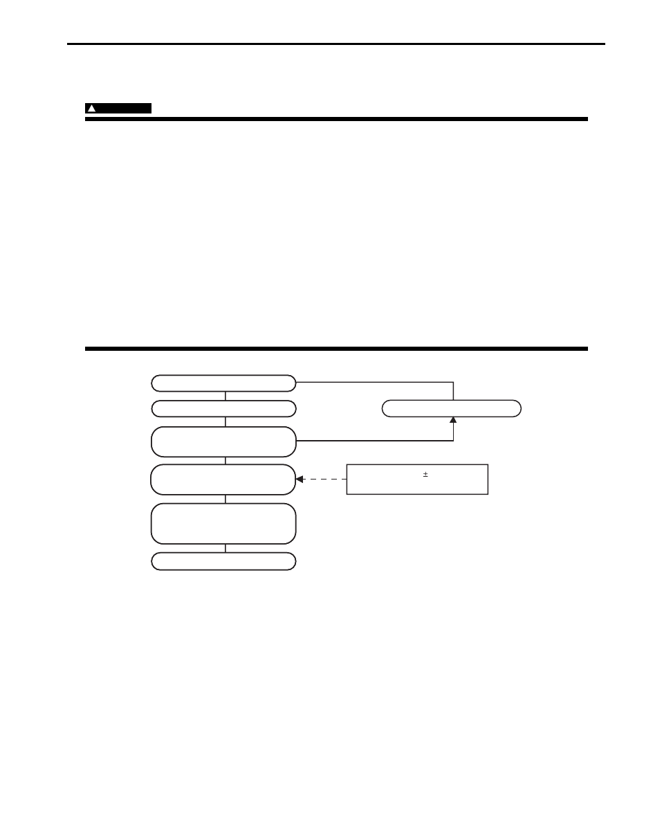
Operation Procedure for Charging A/C with Refrigerant
S6JB0B7206001
WARNING
!
• Your eyes should not be exposed to refrigerant (liquid).
Any liquid Refrigerant-134a escaping by accident shows a temperature as low as approx. –6
°C (21.2
°F) below freezing point. Should liquid HFC-134a (R-134a) get into your eyes, it may cause a serious
injury. To protect your eyes against such accident, it is necessary to always wear goggles. Should it
occur that HFC-134a (R-134a) strikes your eye(s), consult a doctor immediately.
– Do not use your hand to rub the affected eye(s). Instead, use quantities of fresh cold water to
splash it over the affected area to gradually raise temperature of such area above freezing point.
– Obtain proper treatment as soon as possible from a doctor or eye specialist.
• Should the liquid refrigerant HFC-134a (R-134a) is exposed to your skin, the affected area should be
treated in the same manner as when skin is frostbitten or frozen.
• Do not handle refrigerant near any place where welding or steam cleaning is performed.
• Refrigerant should be kept in a cold and dark place. It should never be stored in any place where
temperature is high, e.g. where exposed to direct sun light, close to fire or inside vehicle (including
trunk room).
• Avoid breathing fume produced when HFC-134a (R-134a) is burned. Such fume may be hazardous to
your health.
Star
Start e
t evacuation.
acuation.
Stop e
Stop evacuation.
acuation.
20 min
20 minutes (abo
utes (above 760 mmHg)
e 760 mmHg)
Wait 10 min
ait 10 minutes
utes
Chec
Check A/C system f
k A/C system for
or
pressure tighteness
pressure tighteness.
Recharge A/C system with
Recharge A/C system with
refr
refriger
igerant.
ant.
Chec
Check A/C system f
k A/C system for refr
or refriger
igerant
ant
leaks and amount of refr
leaks and amount of refriger
igerant
ant
charged.
charged.
Perf
erfor
ormance test
mance test
Inspect and repair connections
Inspect and repair connections.
If gauge sho
If gauge shows
ws
abnor
abnormal conditions
mal conditions
Recharge 570 30 g of
Recharge 570 30 g of
refr
refriger
igerant.
ant.
I5JB0A720031-02
Нет комментариевНе стесняйтесь поделиться с нами вашим ценным мнением.
Текст