Suzuki Grand Vitara JB627. Manual — part 75
1B-6 Aux. Emission Control Devices:
PCV Valve Removal and Installation
S6JB0B1206007
Removal
1) Disconnect PCV hose from PCV valve.
2) Remove PCV valve from cylinder head cover.
Installation
1) Apply sealant to thread part of PCV valve (1).
“A”: Water tight sealant 99000–31250 (SUZUKI
Bond No.1207F)
2) Install PCV valve (1) onto cylinder head cover.
Tightening torque
PCV valve (a): 27 N·m (2.7 kgf-m, 19.5 lb-ft)
3) Connect PCV hose (2) to PCV valve (1).
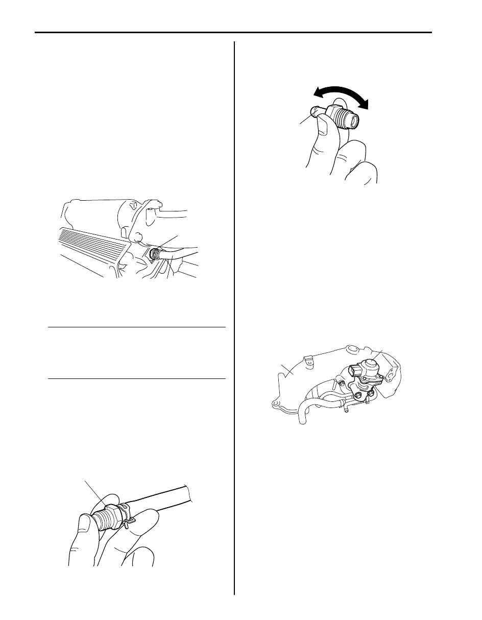
PCV Valve Inspection
S6JB0B1206008
NOTE
Be sure to check that there is no obstruction
in PCV valve or its hoses before checking
engine idle speed / IAC duty for obstructed
PCV valve or hose hampers its accurate
checking.
1) Remove PCV valve referring to “PCV Valve Removal
2) Connect PCV valve (1) to PCV hose and plug head
cover hole.
3) Run engine at idle.
4) Place your finger on the hole of PCV valve (1) to
check for vacuum. If there is no vacuum, check for
clogged valve. Replace as necessary.
5) After checking vacuum, stop engine and remove
PCV valve (1). Shake valve and listen for the rattle of
check needle inside the valve. If valve does not
rattle, replace valve.
6) After inspection, remove plug from head cover hole.
Then, install PCV valve to head cover hole referring
to “PCV Valve Removal and Installation”, connect
PCV valve, PCV hose and clamp securely.
EGR Valve Assembly Removal and Installation
(If Equipped)
S6JB0B1206009
Removal
1) Remove intake collector from intake manifold
referring to Step 1) to 11) of “Intake Collector and
Intake Manifold Removal and Installation in Section
1D”.
2) Remove EGR valve (1) and gasket from intake
collector (2).
Installation
Reverse removal procedure noting the following.
• Clean mating surface of valve and intake collector.
• Use new gaskets.
2
1, “A”, (a)
I4JA01121011-01
1
I5JA01121009-01
1
I4JA01121012-01
1
2
I6JB01120019-01
Aux. Emission Control Devices: 1B-7
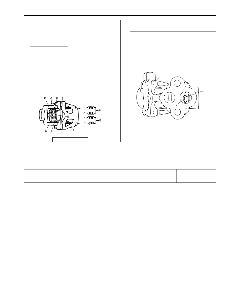
EGR Valve Assembly Inspection (If Equipped)
S6JB0B1206010
1) Check resistance between the following terminals of
EGR valve (1) in each pair.
If found faulty, replace EGR valve assembly.
EGR valve resistance
Terminal “A” and terminal “B”: 20 – 24
Ω at 20 °C
(68
°F)
Terminal “C” and terminal “B”: 20 – 24
Ω at 20 °C
(68
°F)
Terminal “F” and terminal “E”: 20 – 24
Ω at 20 °C
(68
°F)
Terminal “D” and terminal “E”: 20 – 24
Ω at 20 °C
(68
°F)
Terminal “B” and valve body: infinity (
∞)
Terminal “E” and valve body: infinity (
∞)
2) Remove carbon from EGR valve gas passage.
NOTE
Do not use any sharp-edged tool to remove
carbon.
Be careful not to damage or bend EGR valve,
valve seat and rod.
3) Inspect valve (2), valve seat (3) and rod for fault,
cracks bend or other damage.
If found faulty, replace EGR valve (1) assembly.
Specifications
Tightening Torque Specifications
S6JB0B1207001
Reference:
For the tightening torque of fastener not specified in this section, refer to “Fastener Information in Section 0A”.
2. Connector
IYSQ01113035-01
IYSQ01120003-01
Fastening part
Tightening torque
Note
N
⋅m
kgf-m
lb-ft
PCV valve
27
2.7
19.5
1B-8 Aux. Emission Control Devices:
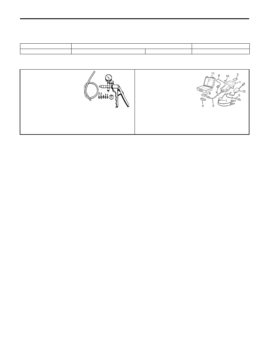
Special Tools and Equipment
Recommended Service Material
S6JB0B1208001
Special Tool
S6JB0B1208002
Material
SUZUKI recommended product or Specification
Note
Water tight sealant
SUZUKI Bond No.1207F
P/No.: 99000–31250
09917–47011
SUZUKI scan tool
Vacuum pump gauge
—
This kit includes following
items. 1. Tech 2, 2. PCMCIA
card, 3. DLC cable, 4. SAE
16/19 adapter, 5. Cigarette
cable, 6. DLC loop back
adapter, 7. Battery power
cable, 8. RS232 cable, 9.
RS232 adapter, 10. RS232
loop back connector, 11.
Storage case, 12. ) / )

Engine Electrical Devices: 1C-1
Engine
Engine Electrical Devices
Repair Instructions
Engine Control Module (ECM) Removal and
Installation
S6JB0B1306001
CAUTION
!
As ECM consists of precision parts, be
careful not to expose it to excessive shock.
NOTE
If ECM is replaced with new one or with
another one, make sure to register
immobilizer transponder code to ECM
correctly according to “Procedure after ECM
Replacement in Section 10C”.
Removal
1) Disconnect negative cable from battery.
2) Remove ECM cover from bracket.
3) Disconnect connectors from ECM as follows.
a) Push lock (1) to release locking of lock lever (2).
b) Turn lock lever to arrow direction until it stops.
4) Remove ECM (1) from its bracket by removing its
mounting bolts (2).
Installation
Reverse removal procedure noting the following:
• Connect connectors to ECM as follows.
a. Make sure that lock lever (1) of ECM connector is
at unlock position.
b. In this state, insert connectors to ECM securely.
c. Lock ECM connectors securely by turning its lock
lever to left until it stops.
1
2
I6JB01130001-02
2
1
I6JB01130002-03
1
I6JB01130003-01
Нет комментариевНе стесняйтесь поделиться с нами вашим ценным мнением.
Текст