Suzuki Grand Vitara JB627. Manual — part 113
1I-6 Starting System:
Starting Motor Dismounting and Remounting
S6JB0B1906002
Dismounting
1) Disconnect negative (–) cable at battery.
2) Dismounting generator referring to “Generator
Dismounting and Remounting in Section 1J”.
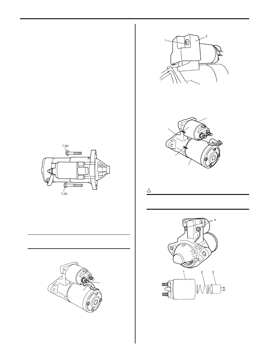
3) Disconnect magnetic switch lead wire and battery
cable from starting motor terminals.
4) Remove 2 starting motor mount bolts.
5) Remove starting motor.
Remounting
Reverse the dismounting procedure noting the following.
• Tighten starting motor mount bolt (1) and starting
motor battery cable nut.
Tightening torque
Starting motor mount bolt (a): 55 N·m (5.5 kgf-m,
40.0 lb-ft)
Starting motor battery cable nut: 11 N·m (1.1 kgf-m,
8.0 lb-ft)
Starting Motor Disassembly and Assembly
S6JB0B1906003
Disassembly
NOTE
Do not clamp yoke in a vise or strike it with a
hammer during repair operations.
1) Disconnect lead wire (1) from terminal “M” (2).
2) Loosen screws (1) and then remove protector (2).
3) Put match marks at 2 locations (A (magnetic switch
(1) and front housing (2)) and B (front housing (2)
and yoke (3))) as shown in figure so that any
possible mistake can be avoided.
4) Loosen screws (4) and then remove magnetic switch
(1), spring (2) and plunger (3).
CAUTION
!
Don’t disassemble magnetic switch. If
defective, replace as a complete assembly.
I6JB01190018-01
2
1
I6JB01190007-01
I6JB01190008-01
1
2
3
A
B
I6JB01190009-01
I6JB01190010-01
Starting System: 1I-7
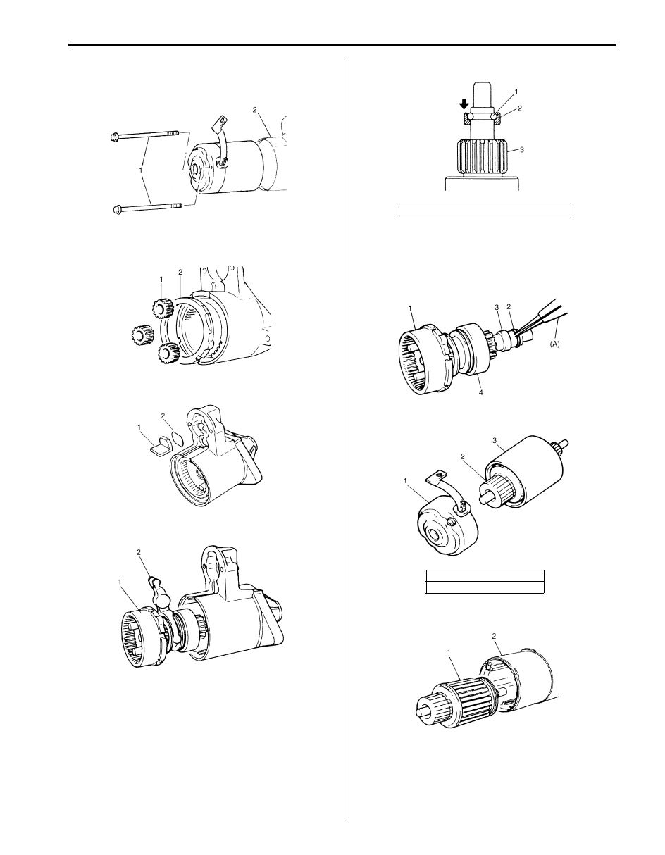
5) Remove through bolts (1) shown in the figure, then
separate reduction gear assembly (2) from starting
motor assembly.
6) To overhaul reduction gear assembly, remove
packing (2) and planetary gears (1).
7) Remove seal rubber (1) and plate (2).
8) Remove shaft assembly (1) with lever (2).
9) Loosen pinion stop ring (2) fixed by snap ring (1).
10) Remove snap ring (2), then pull out pinion stop ring
(3) and over-running clutch (4) and internal gear (1).
Special tool
(A): 09900-06107
11) Remove rear bracket (1) and brush holder.
12) Remove armature (1) from yoke (2).
I6JB01190011-01
IYSQ01190012-01
I6JB01190012-01
IYSQ01190014-01
3. Over-running clutch assembly
2. Armature
3. Yoke
IYSQ01190015-01
IYSQ01190016-01
IYSQ01190017-01
I6JB01190013-01
1I-8 Starting System:
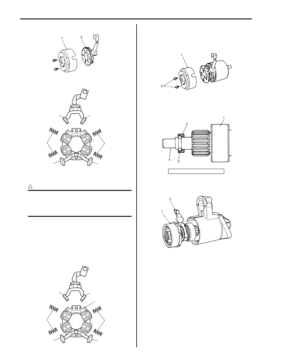
13) Remove brush holder (2) from rear bracket (1).
14) Remove brush springs (1) and brushes (2).
Assembly
CAUTION
!
New oilless bearing have been lubricated
when they are supplied as spare parts.
DO NOT wash with grease dissolving solvent
nor lubricate them with other lubricant.
1) Inspect component parts referring to “Starting Motor
Inspection” and replace with new ones as necessary.
2) Apply grease referring to “Starting Motor
3) Install armature to yoke.
4) Install brushes (1) and brush springs (2) to brush
holder (3).
5) Install brush holder to armature while pushing 4
brushes outward.
6) Install rear bracket (1).
7) Tighten brush holder screws (2).
8) Install internal gear and over-running clutch
assembly (1) to gear shaft (4), using care for
installing direction of pinion stop ring (2).
9) Insert shaft assembly (1) into front housing with lever
(2) positioned as shown in the figure.
IYSQ01190019-01
1
1
2
2
1
1
I6JB01190014-01
1
1
2
2
1
1
3
I6JB01190015-01
3. Snap ring
IYSQ01190023-01
IYSQ01190024-01
IYSQ01190014-01
Starting System: 1I-9
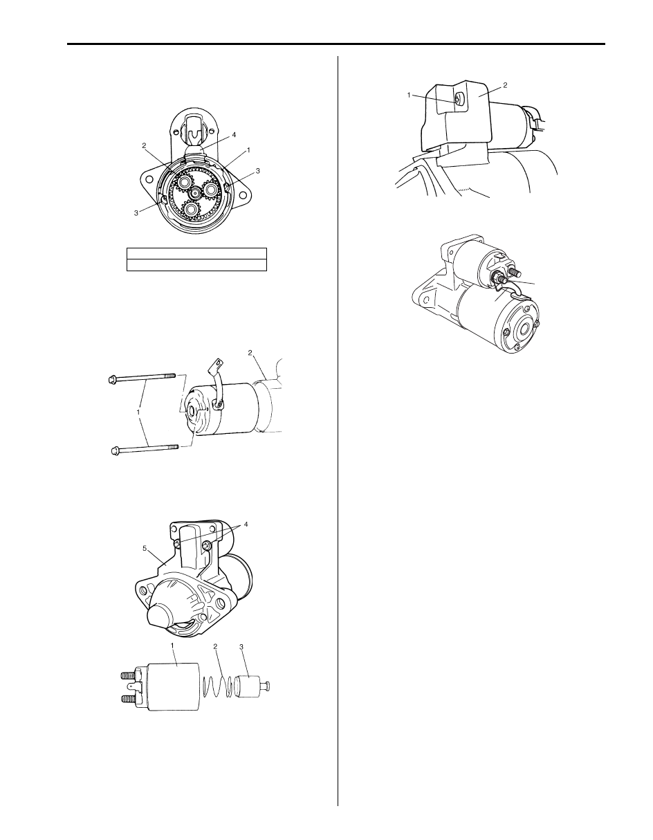
10) Install packing (1) so that cuts in packing align with
holes for through bolts in front housing.
11) Install plate and seal rubber (4) to front housing.
12) Install yoke, armature, brush holder and rear bracket
to front housing (2) by aligning match marks
provided before removal.
13) Tighten through bolts (1).
14) Install magnetic switch (1), spring (2) and plunger (3)
to front housing (5) by aligning match marks
provided before removal and then tighten screws (4).
15) Install protector (2) and tighten screws (1).
16) Connect lead wire (1) to terminal “M” (2).
17) Upon completion of assembly, carry out performance
test. Refer to “Starting Motor Performance Test”.
2. Planetary gear
3. Bolt hole
IYSQ01190025-01
I6JB01190011-01
I6JB01190016-01
I6JB01190008-01
2
1
I6JB01190007-01
Нет комментариевНе стесняйтесь поделиться с нами вашим ценным мнением.
Текст