Suzuki Grand Vitara JB627. Manual — part 437
10E-33 Keyless Start System:
Repair Instructions
Antennas and Request Switches Removal and Installation
S6JB0BA506001
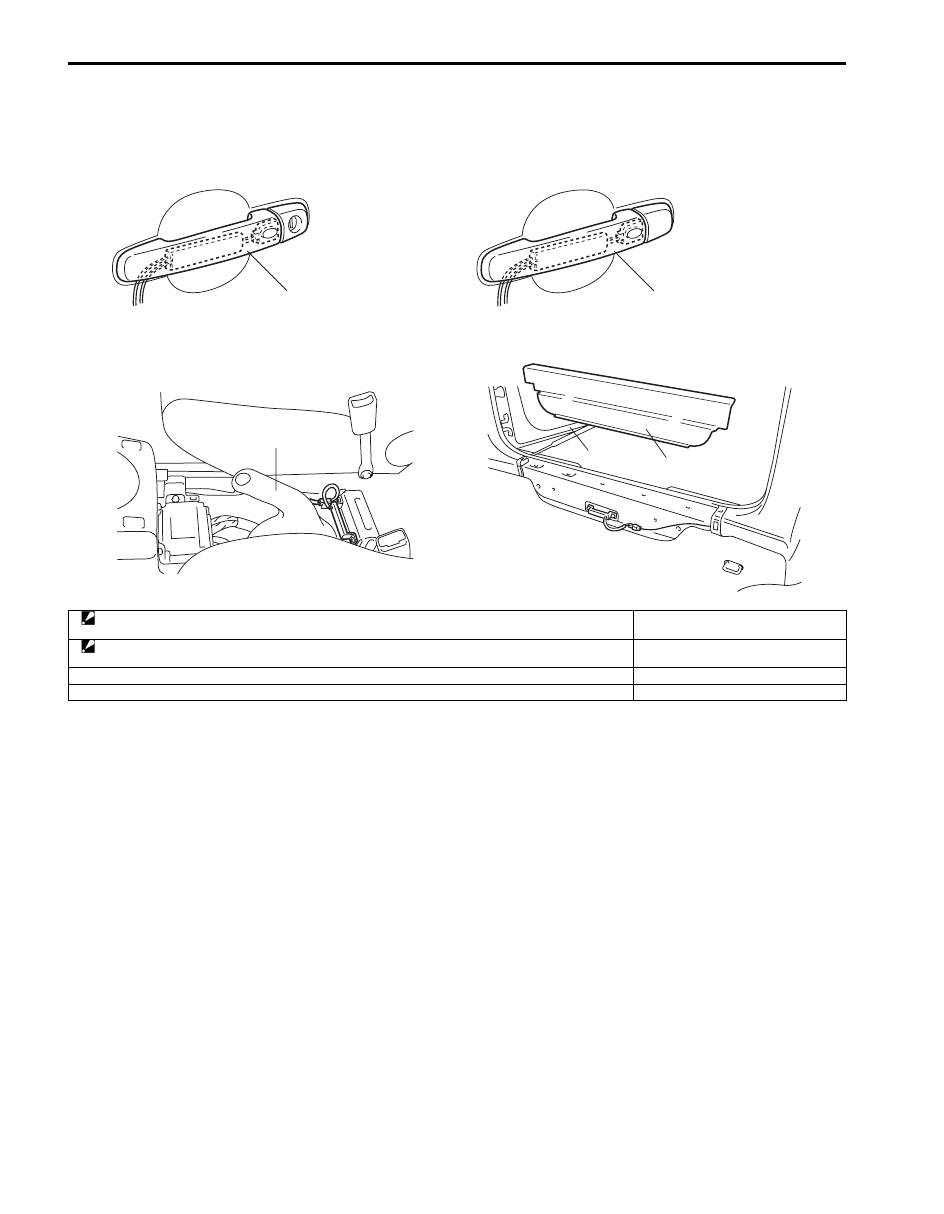
Remove and install antennas and request switches referring to the following figures.
[A]
[B]
[C]
[D]
1
1
2
3
4
I5JB0AA50019-01
[A]: Driver side door antenna and request switch (included in outside door handle assembly)
: Antenna and request switch can not be removed from outside door handle assembly
1. Outside handle assembly
[B]: Passenger side or rear end door antenna and request switch (included in outside door handle assembly)
: Antenna and request switch can not be removed from outside door handle assembly
2. Parking brake lever
[C]: Center antenna
3. Tail end member trim
[D]: Luggage room antenna
4. Rear end door

Keyless Start System: 10E-34
Front Door (Driver and Passenger Side), Rear
End Door Request Switch Inspection
S6JB0BA506002
1) Remove door trim from door panel.
For front door trim, refer to Step 1) to 3) of “Front
Door Glass Removal and Installation in Section 9E”.
For rear end door trim, refer to Step 1) of “Rear End
Door Lock Assembly Removal and Installation in
Section 9F”.
2) Check for continuity between terminals “1” and “2” at
each switch position as shown below. If check result
is not as specified, replace.
Request switch (1) specification
ON position (request switch pushed): Continuity
OFF position (request switch released): No
continuity
Steering Lock Unit Removal and Installation
S6JB0BA506003
For removal and installation, refer to “Steering Lock
Assembly (Ignition Switch) Removal and Installation in
Section 6B”.
Steering Lock Unit Inspection
S6JB0BA506004
Check key reminder switch and ignition knob switch in
steering lock unit for operation referring to “Ignition
Switch Inspection in Section 9C”.
Front Door Lock Switch Inspection
S6JB0BA506005
1) Remove door trim from door panel referring to Step
1) to 3) of “Front Door Glass Removal and
Installation in Section 9E”.
2) Check for continuity between terminals “1” and “2” at
each switch position as shown below. If check result
is not as specified, replace.
Door lock switch specification
LOCK position: No continuity
UNLOCK position: Continuity
2. Outside handle
1
“2”
“1”
2
I5JB0AA50020-01
[A]: Lock
[B]: Unlock
“1”
“2”
[B]
[A]
I5JB0AA50021-02
10E-35 Keyless Start System:
Keyless Start Control Module Removal and
Installation
S6JB0BA506006
Removal
1) Disconnect negative cable at battery.
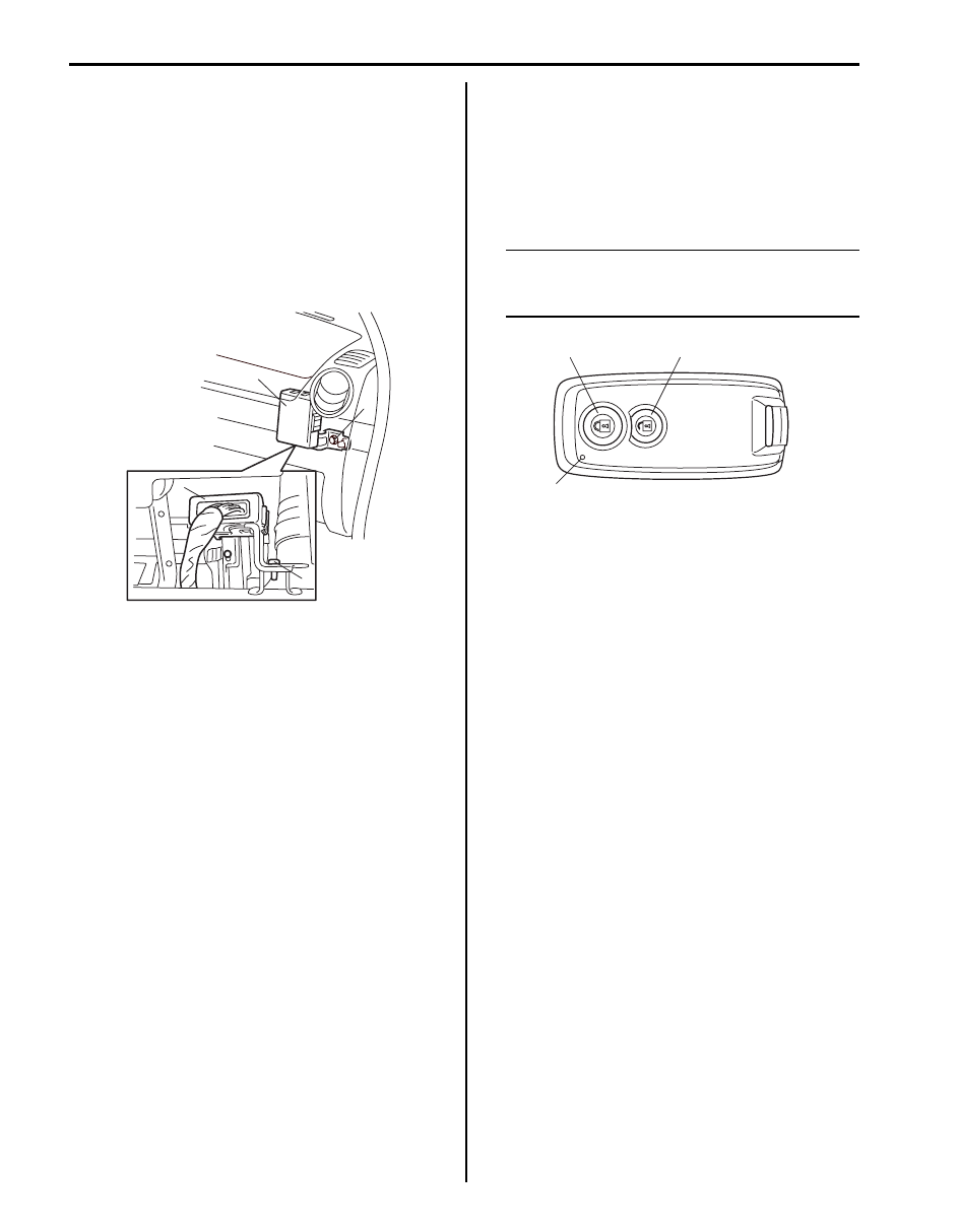
2) Remove glove box from instrument panel.
3) Disconnect connector from keyless start control
module (1).
4) Remove keyless start control module mounting bolt
(2) and then remove keyless start control module
with its bracket from steering support member.
Installation
For installation, reverse removal procedure.
If keyless start control module is replaced, register ID
code of remote controller into keyless start control
module, referring to “Registration Procedure for Remote
Controller ID Code”.
Remote Controller Inspection
S6JB0BA506007
Check that remote controller operation indicator light (3)
lights up when lock (1) or unlock (2) button of remote
controller is pushed.
If it doesn’t light up in this check, replace battery and
then recheck. If it doesn’t light up even after battery
replacement, replace remote controller.
NOTE
When remote controller transmits lock or
unlock signal, it makes operation indicator
light light up.
1
1
2
2
I5JB0AA50022-01
1
2
3
I4RS0BA50031-01
Keyless Start System: 10E-36
Replacement of Remote Controller Battery
S6JB0BA506008
If remote controller operation indicator light fails to light
up when lock or unlock button of remote controller is
pushed, replace its battery as follows.
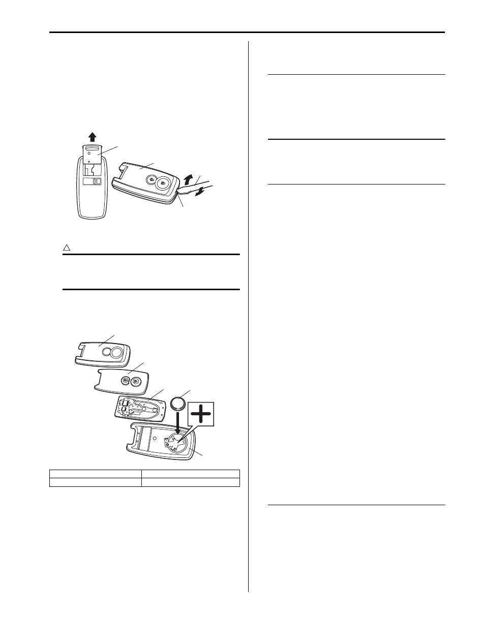
1) If ignition key (1) is inserted in remote controller,
remove it.
2) With tip of flat blade screwdriver (2) put in slot (3) of
remote controller (4), pry it open.
3) Remove battery (4) from lower case (5).
CAUTION
!
Use care not to allow grease or dirt to be
attached on the printed circuit board and the
battery.
4) Replace the battery (lithium disc-type CR 2032 or
equivalent battery) so its (+) terminal faces on
remote controller lower case.
5) Install printed circuit board and rubber switch to
upper case and then fit lower case securely.
NOTE
• To prevent theft, be sure to break the
remote controller before discarding it.
• Dispose of the used battery properly
according to applicable rules or
regulations. Do not dispose of lithium
batteries with ordinary household trash.
Registration Procedure for Remote Controller
ID Code
S6JB0BA506009
NOTE
• It is possible to register up to 4 remote
controllers in keyless start control module.
• Setting keyless start control module to ID
code registration mode of remote
controller will erase all remote controller ID
codes that have been registered in keyless
start control module.
Therefore, when registering remote
controller ID codes in keyless start control
module, have all of those to be registered
ready and execute their registration at the
same time.
• When registration of more than four
remote controller ID codes is attempted,
the oldest remote controller ID code will be
erased and that inputted after the fourth
one will be registered.
• When keyless start control module which
was used in another vehicle has been
installed, register the ID code of the remote
controller to the keyless start control
module first and then the following code.
– With immobilizer control system,
register the ignition key transponder
code for the immobilizer control system
in ECM. For registration procedure of
that, refer to “Registration of the Ignition
Key in Section 10C”.
– Without immobilizer control system,
register the steering lock unit ID code in
keyless start control module. For
registration procedure of that, refer to
“Keyless Start Registration”.
1. Upper case
3. Printed circuit board
2. Rubber switch
1
4
2
3
I4RS0BA50032-01
1
2
3
4
5
I4RS0BA50033-01
Нет комментариевНе стесняйтесь поделиться с нами вашим ценным мнением.
Текст