Suzuki Grand Vitara JB627. Manual — part 436

10E-29 Keyless Start System:
DTC Detecting Condition and Trouble Area
DTC Confirmation Procedure
1) Clear DTC referring to “DTC Clearance”.
2) Turn ignition key knob by pushing ignition key knob.
3) Check DTC referring to “DTC Check”.
Troubleshooting
DTC detecting condition
Trouble area
Keyless start control module cannot receive data sent by
CAN from BCM.
• CAN communication circuit
• Keyless start control module
• BCM
Step
Action
Yes
No
1
Was “Keyless Start System Check” performed?
Go to Step 2.
Go to “Keyless Start
System Check”.
2
DTC Check of keyless start control module
Is DTC No. 33 detected?
Go to “DTC No. 33:
Control Module
Communication Bus
Off”.
Go to Step 3.
3
DTC Check of BCM
1) Check BCM for DTC referring to “DTC Check in Section
Is DTC U1073, DTC U1100 or DTC U1101 detected?
Go to applicable DTC
diag flow.
Go to Step 4.
4
CAN communication circuit check
1) Check connection of connectors of all control modules
communicating by means of CAN.
2) Disconnect connectors from BCM and keyless start
control module.
3) Check CAN communication circuit between BCM and
keyless start control module for open, short and high
resistance.
Is each CAN communication circuit in good condition?
Go to Step 5.
Repair circuit.
5
CAN communication circuit check
1) Disconnect connectors of all control modules
communicating by means of CAN.
2) Check CAN communication circuit between control
modules other than Step 4 for open, short and high
resistance.
Is each CAN communication circuit in good condition?
Go to Step 6.
Repair circuit.
6
DTC check of ECM
1) Connect connectors of disconnected control modules
communicating by means of CAN.
2) Check ECM for DTC.
Is DTC U0140 detected?
Check BCM power and
ground circuit. If circuit
is OK, substitute a
known-good BCM and
recheck.
Go to Step 7.

Keyless Start System: 10E-30
DTC No. 33: Control Module Communication Bus Off
S6JB0BA504021
Wiring Diagram
Refer to “DTC No. 31: Lost Communication with BCM”.
DTC Detecting Condition and Trouble Area
DTC Confirmation Procedure
1) Clear DTC referring to “DTC Clearance”.
2) Start engine and run it for 1 min. or more.
3) Check DTC referring to “DTC Check”.
Troubleshooting
7
DTC check of keyless start control module
1) Turn ignition switch to OFF position.
2) Disconnect connector of any one of control module other
than keyless start control module.
3) Recheck keyless start control module for DTC.
Is DTC No.31 detected?
Using same method,
disconnect connectors
of control module other
than keyless start
control module one by
one to check if DTC
No.31 is detected.
If DTC No.31 is
detected even through
connector of control
module other than
keyless start control
module is disconnected,
substitute a known-
good keyless start
control module and
recheck.
Check power and
ground circuit of
disconnected control
module and recheck. If
circuit is OK, substitute
a known-good
disconnected control
module and recheck.
Step
Action
Yes
No
DTC detecting condition
Trouble area
Communication is not available with all control modules
connected by CAN.
• CAN communication circuit
• Combination meter
• Keyless start control module
• BCM
• 4WD control module (if equipped)
• ABS or ESP
® control module
• TCM (A/T model)
• ECM
• Steering angle sensor (if equipped)
Step
Action
Yes
No
1
Was “Keyless Start System Check” performed?
Go to Step 2.
Go to “Keyless Start
System Check”.
2
Control module connector check
1) Check connection of connectors of all control modules
communicating by means of CAN.
2) Recheck keyless start control module for DTC.
Is DTC No. 33 detected?
Go to Step 3.
Intermittent trouble.
Check for intermittent
referring to “Intermittent
and Poor Connection
Inspection in Section
00”.
10E-31 Keyless Start System:
DTC No. 51 / No. 52 / No. 53: Driver Side / Passenger Side / Rear End Door Request Switch Failure
S6JB0BA504022
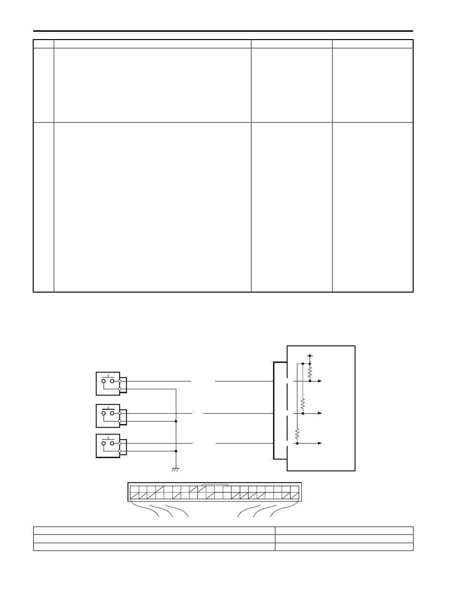
Wiring Diagram
3
CAN communication circuit check
1) Turn ignition switch to OFF position.
2) Disconnect connectors of all control modules
communicating by means of CAN.
3) Check CAN communication circuit between control
modules for open, short and high resistance.
Is each CAN communication circuit in good condition?
Go to Step 4.
Repair circuit.
4
DTC check of keyless start control module
1) Turn ignition switch to OFF position.
2) Connect connectors of disconnected control modules
communicating by means of CAN.
3) Disconnect connector of any one control module other
than keyless start control module.
4) Recheck keyless start control module for DTC.
Is DTC No.33 detected?
Using same method,
disconnect connectors
of control module other
than keyless start
control module and
combination meter one
by one to check if DTC
No.33 is detected.
If DTC No.33 is
detected even though
connector of control
module other than
keyless start control
module and
combination meter is
disconnected, substitute
a known-good keyless
start control module and
recheck.
Check power and
ground circuit of
disconnected control
module. If circuit is OK,
substitute a known-
good disconnected
control module and
recheck.
Step
Action
Yes
No
G44
[A]
1
2
3
4
5
6
7
8
9
10
11
14
15
16
36
34 33 32
30 29
24 23
37
18
19
20
RED/BLK
BLU
YEL/RED
G44-16
G44-36
G44-32
12V
1
2
3
4
I5JB0AA50018-02
[A]: Keyless start control module connector (viewed from harness side)
3. Passenger side door request switch
1. Keyless start control module
4. Rear end door request switch
2. Driver side door request switch

Keyless Start System: 10E-32
DTC Detecting Condition and Trouble Area
DTC Confirmation Procedure
1) Clear DTC referring to “DTC Clearance”.
2) Push request switch of each door.
3) Check DTC referring to “DTC Check”.
Troubleshooting
DTC detecting condition
Trouble area
DTC No. 51:
Input signal from driver side door request switch remains
ON, unchanged for 10 minutes or longer.
DTC No. 52:
Input signal from passenger side door request switch
remains ON, unchanged for 10 minutes or longer.
DTC No. 53:
Input signal from rear end door request switch remains
ON, unchanged for 10 minutes or longer.
• Driver side door request switch and its circuit
• Passenger side door request switch and its circuit
• Rear end door request switch and its circuit
• Keyless start control module
Step
Action
Yes
No
1
Was “Keyless Start System Check” performed?
Go to Step 2.
Go to “Keyless Start
System Check”.
2
Request switch check
1) Check related door request switch for function referring
to “Front Door (Driver and Passenger Side), Rear End
Door Request Switch Inspection”.
Is each switch in good condition?
Go to Step 3.
Replace request switch.
3
Wire harness check
1) Disconnect connector from keyless start control module.
2) Check for open, short and high resistance in related door
request switch circuit.
Is each circuit in good condition?
Substitute a known-
good keyless start
control module and
recheck.
Repair circuit.
Нет комментариевНе стесняйтесь поделиться с нами вашим ценным мнением.
Текст