Suzuki Grand Vitara JB627. Manual — part 375
9B-25 Lighting Systems:
License Light Assembly Removal and
Installation
S6JB0B9206015
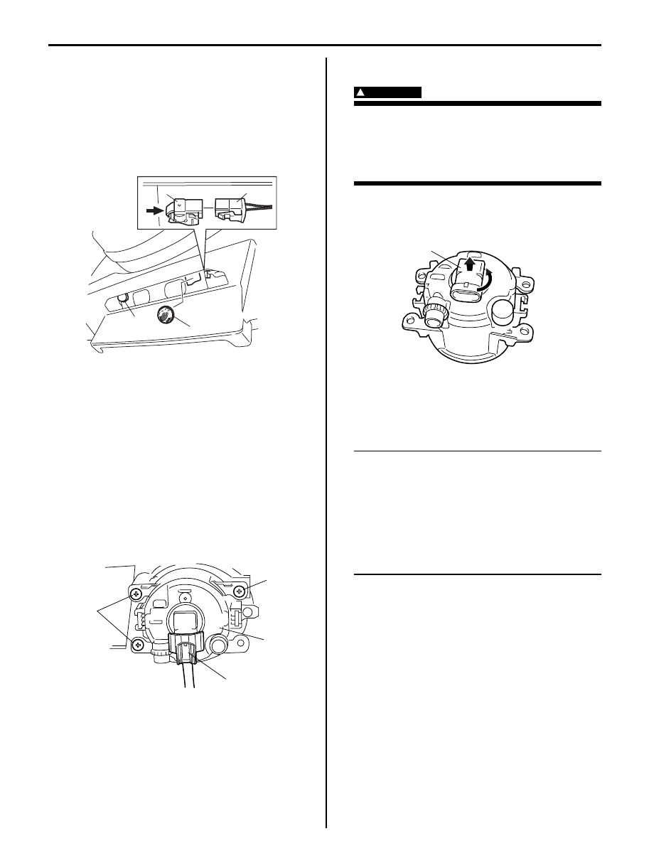
Removal
1) Disconnect negative (–) cable at battery.
2) Disconnect coupler (1) from license light (2).
3) Push locking part to arrow direction, and then
remove license light (2).
Installation
Reverse removal procedure for installation.
Front Fog Light Assembly Removal and
Installation (If Equipped)
S6JB0B9206016
Removal
1) Disconnect negative (–) cable at battery.
2) Remove front bumper. Refer to “Front Bumper
3) Disconnect coupler (1) from fog light (2).
4) Remove fog light screws (3), and remove front fog
light assembly (2).
Installation
Reverse removal procedure for installation nothing the
following:
• After installing, adjust aiming referring to “Front Fog
Light Aiming Adjustment with Screen (If Equipped)”.
Front Fog Light Bulb Replacement (If Equipped)
S6JB0B9206017
WARNING
!
• To avoid danger of being burned, don’t
touch when the bulb is hot.
• Don’t touch glass surface of bulb to avoid
deteriorate as the case may be unclear
when bulb light on at dirty condition.
1) Remove front bumper referring to “Front Bumper
2) Remove fog light bulb (1) as shown.
3) Replace fog light bulb and assemble all removed
parts.
Front Fog Light Switch Inspection (If Equipped)
S6JB0B9206018
NOTE
Front fog lights light up only when headlight
switch is in HEADLIGHT position (low or high
beams) or SMALL position. Front fog lights
turn OFF automatically when headlight
switch is turned to OFF position. If front fog
light switch holds ON position, front fog
lights turn ON automatically when headlight
switch is tuned to HEADLIGHT position (low
or high beams) or SMALL position again.
2
1
2
2
I5JB0A920028-01
3
3
1
2
I4RS0A920019-01
1
I4RS0A920020-01
Lighting Systems: 9B-26
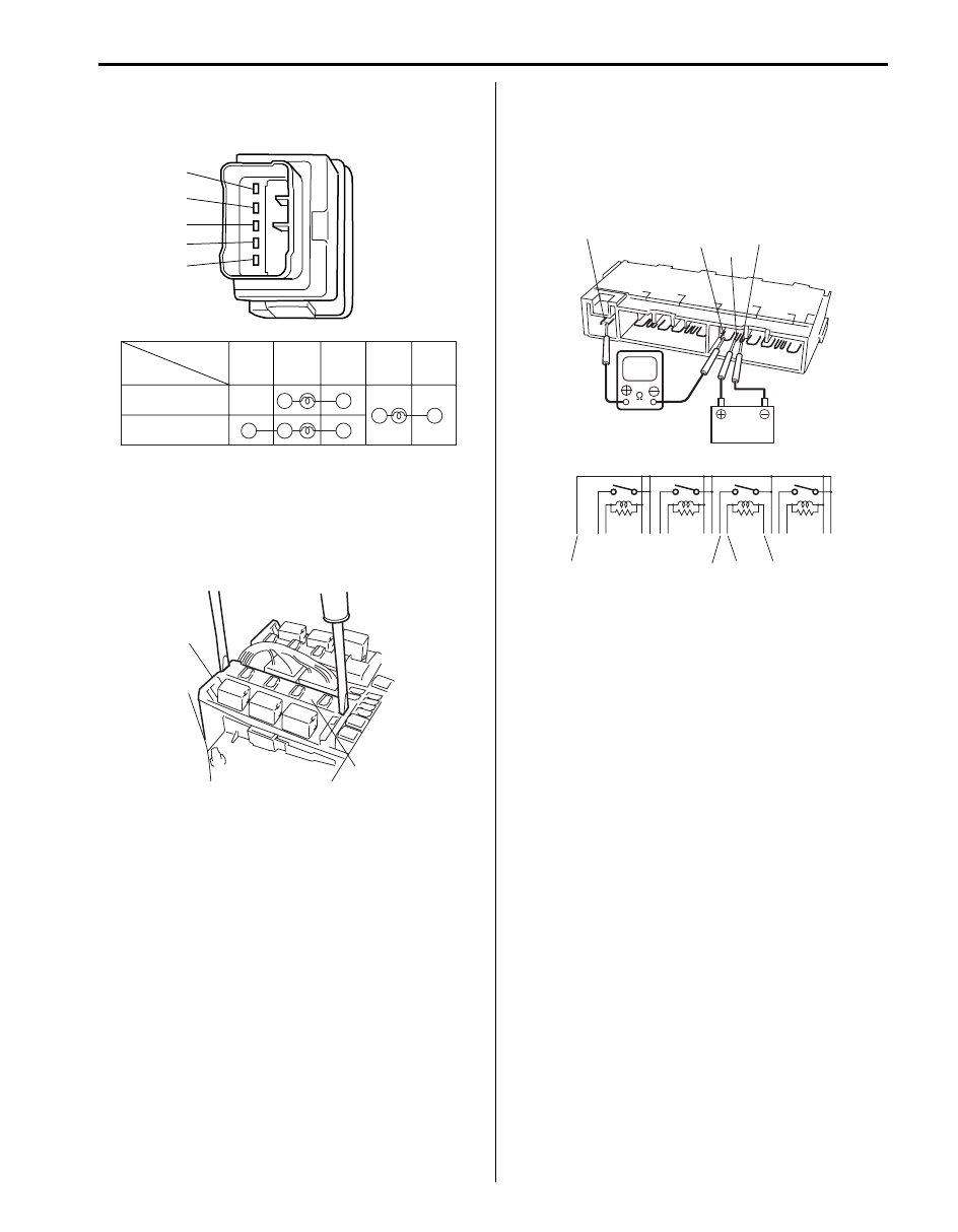
Check for continuity between terminals at each switch
position. If check result is not as specified, replace
switch.
Front Fog Light Relay Inspection (If Equipped)
S6JB0B9206019
1) Disconnect negative (–) cable from battery.
2) Remove front fog light relay (included in integration
relay) (1) from main fuse box (2).
3) Check that there is no continuity between terminals
“a” and “b”.
If there is continuity, replace relay.
Check that there is continuity between terminals “a”
and “b” when a 12 V battery is connected to terminal
“c” and “d”.
If malfunction is found, replace integration relay.
1
2
3
4
5
Switch Position
Terminal
ON (PUSH IN)
2
3
1
5
4
OFF
I4RS0A920021-01
2
1
I5JB0A920029-01
“a”
“c”
“b”
“a”
“c”
“d”
“b”
“d”
I5JB0A920030-03
9B-27 Lighting Systems:
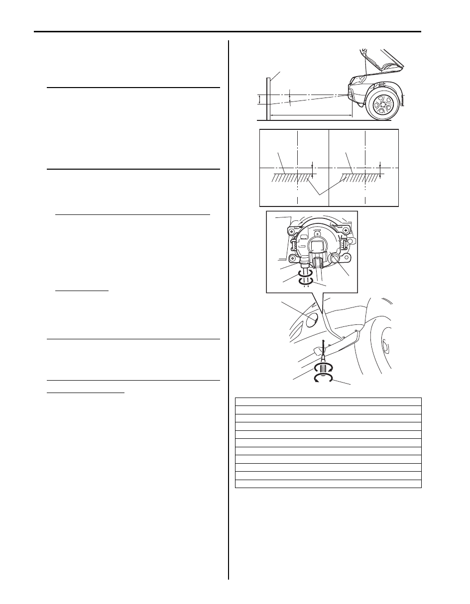
Front Fog Light Aiming Adjustment with Screen
(If Equipped)
S6JB0B9206020
Basic Aiming
NOTE
• Unless otherwise obligated by local
regulations, adjust front fog light aiming
according to the following procedure.
• An example in case that the light-to-wall
distance 10 m is shown in the illustration.
The beam descending distance “H” is
calculated when “a” is 10 m with the
specification angle “b” (1.75
°).
1) Make sure the following items.
• Place vehicle on a flat surface in front of blank wall
(screen) (1) ahead of front fog light surface.
Distance between screen and front fog light
“a”: 10 m (32.8 ft.)
• Adjust air pressure of all tired to the specified
value respectively.
• Bounce vehicle body up and down by hand to
stabilize suspension.
• Carry out aiming with a driver aboard.
Driver’s weight
75 kg (165 lb)
2) Check to see if hot spot (high intensity zone) of each
front fog light axis falls as shown in the figure.
NOTE
If the fog lights interfere each other and make
it hard to see the cut line clearly, cover the
fog light on one side. This helps to make
aiming adjustment easier.
Hot spot specification
Angle “b”: 1.75
° (Specification)
Calculated distance “H”: Approx. 300 mm (11.81
in.)
3) If it is not set properly, align front fog light to
specification by rotating aiming gear.
2. Bounding line
3. Hot spot
4. Aiming gear (for up / down adjustment)
5. Turning (for up adjustment)
6. Turning (for down adjustment)
7. Front fog light assembly
X-X: Horizontal center line of front fog light bulb
A-A: Vertical center line of left front fog light bulb
B-B: Vertical center line of right front fog light bulb
[A]: Left front fog light
[B]: Right front fog light
A
A
X
X
4
2
B
B
[A]
[B]
2
1
5
6
7
4
5
6
7
“a”
“b”
“H”
“H”
“H”
I5JB0A920031-03
Lighting Systems: 9B-28
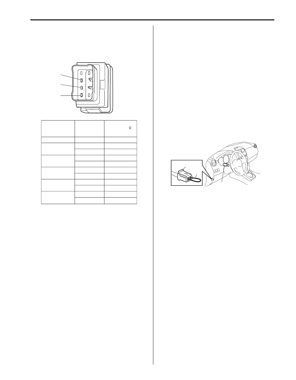
Headlight Manual Leveling Switch (If Equipped)
Inspection
S6JB0B9206021
Check for continuity between terminals at each switch
position.
If check result is not as specified, replace switch.
Headlight Leveling Actuator Inspection (If
Equipped)
S6JB0B9206022
Vehicle Equipped with Headlight Auto Leveling
System
1) Make sure all couplers of headlight and leveling
actuator are connected securely.
2) Park vehicle in front of blank wall (screen).
3) Turn ignition switch to ON position.
4) Perform “Headlight Leveling Warning Light Check”.
5) Connect service wire (2) to terminals of diagnosis
connector (1).
6) Perform Steps a) through c) described below within
20 seconds after Step 5).
a) Turn lighting switch (3) to “HEAD” position and
then turn lighting switch to OFF position.
b) Repeat Step a) 2 times.
c) Turn lighting switch (3) to “HEAD” position.
7) Check that optical axes of headlights reflected on
blank wall (screen) change. If not, go to “Headlight
Auto Leveling System Symptom Diagnosis (If
Equipped)”.
Vehicle Equipped with Manual Leveling Headlight
System
1) Make sure all couplers of headlight and leveling
actuator are connected securely.
2) Park vehicle in front of blank wall (screen).
3) Turn ignition switch to ON position.
4) Turn lighting switch to “HEAD” position.
5) Move manual leveling headlight switch and check
that optical axes of headlights reflected on blank wall
(screen) change then. Also check that leveling
actuator sounds slightly while moving leveling
switch. If optical axes do not change, go to
“Headlight Manual Leveling System Symptom
Diagnosis (If Equipped)”.
1
2
3
Switch Position
0
Terminal
Resistance ( )
-
1
2
3
4
1 and 2
4370 - 4830
1 and 3
2 and 3
1 and 3
2 and 3
1 and 3
2 and 3
1 and 3
2 and 3
1 and 3
2 and 3
646 - 714
3724 - 4116
3078 - 3402
1292 - 1428
1938 - 2142
2584 - 2856
3230 - 3570
2432 - 2688
1786 - 1974
1140 - 1260
I4RS0B920012-01
1
2
3
I5JB0A920032-01
Нет комментариевНе стесняйтесь поделиться с нами вашим ценным мнением.
Текст